
Adhesive material for fuel cell and fuel cell

a fuel cell and adhesive technology, applied in the direction of non-metal conductors, cell components, conductors, etc., can solve the problems of large internal stress likely to occur in the electrolyte membrane, deformation or degradation of dried layers, and insufficient adhesive strength, etc., to achieve the effect of convenient application

Inactive Publication Date: 2013-02-14
TOYOTA JIDOSHA KK
View PDF1 Cites 5 Cited by
  • Summary
  • Abstract
  • Description
  • Claims
  • Application Information

AI Technical Summary

Benefits of technology

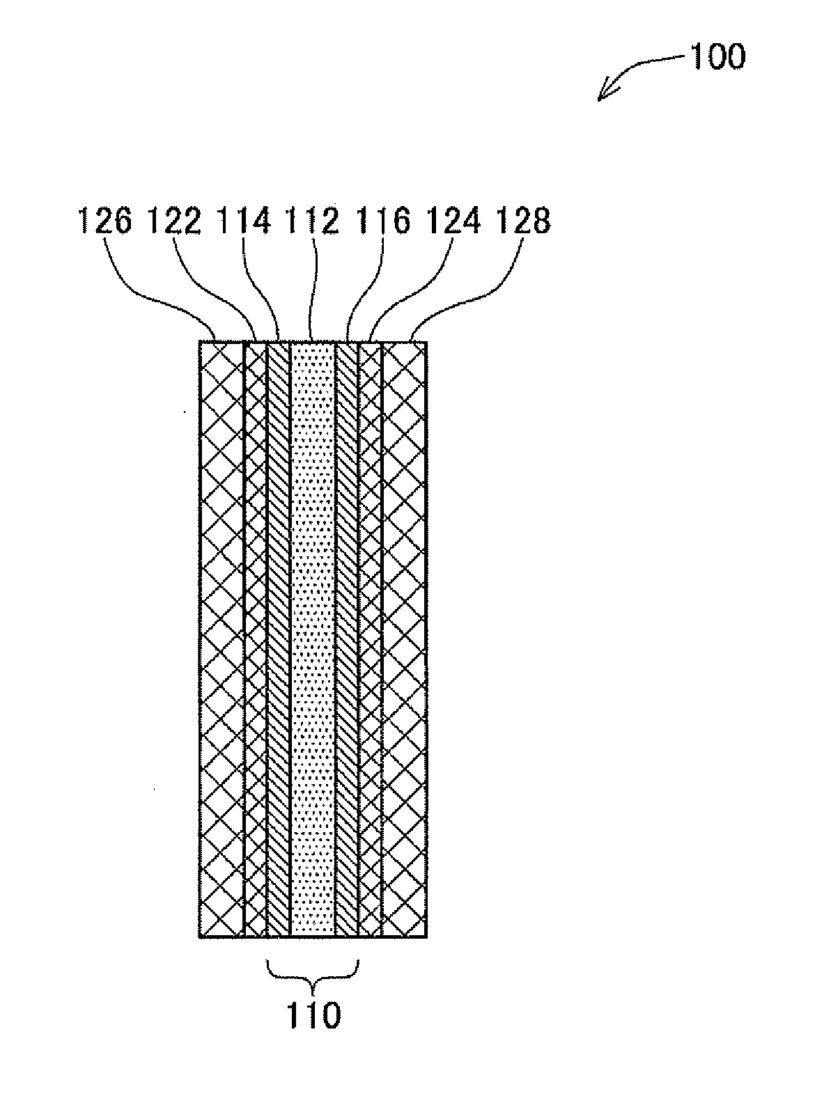
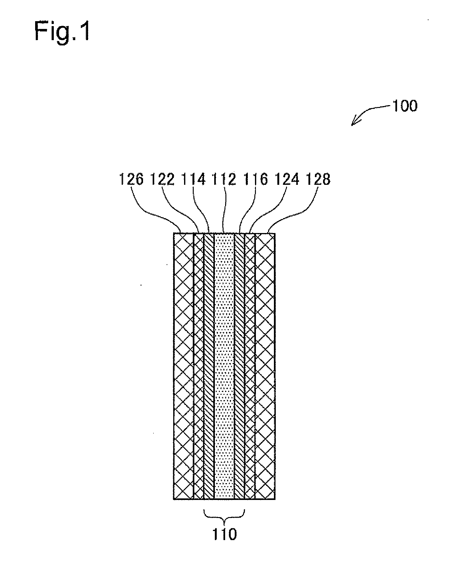
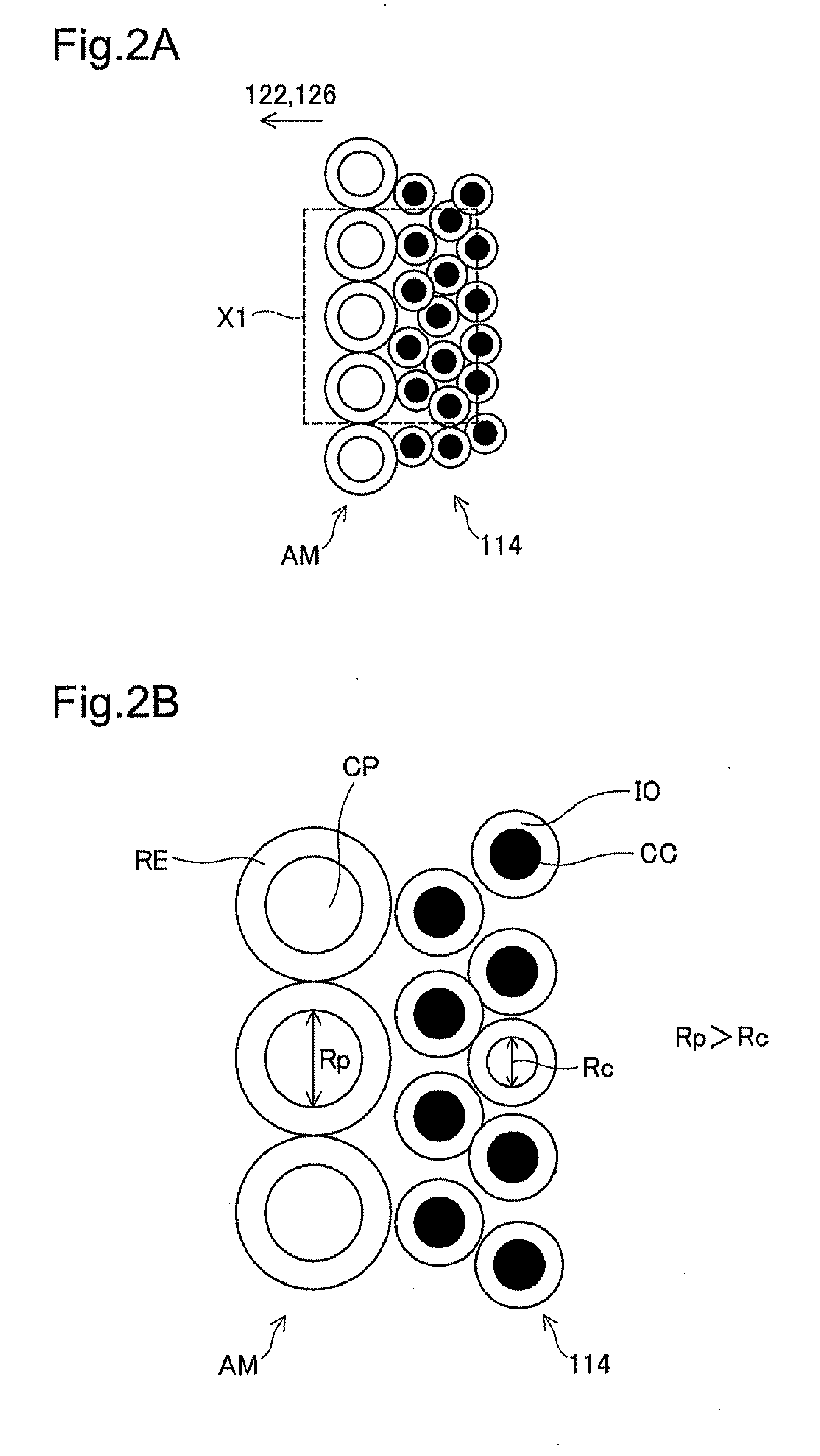
This patent describes an adhesive material used to bond layers of a fuel cell together. The adhesive material contains a conductive resin and conductive particles, which improves adhesiveness and electron conductivity between the layers. The average diameter of the conductive particles is larger than the average diameter of the catalyst support in the fuel cell, which prevents the adhesive material from entering the catalyst layers and maintaining gas diffusivity. This prevents degradation in the performance of the fuel cell.

Problems solved by technology

This proposed method may, however, cause vaporization of water contained in the respective layers of the fuel cell by heat of thermal compression bonding, which may result in deformation or degradation of the dried layers.
Thermal compression bonding also causes the electrolyte membrane in the dried and compressed state to be bonded to other layers, so that a large internal stress is likely to occur in the electrolyte membrane by water absorption during operation of the fuel cell after bonding.
Pressure bonding at ambient temperature that is lower than the glass transition temperature of the ionomer thus results in insufficient adhesive strength.
Additionally, the high electron conductivity (i.e., low electrical resistance) is required in bonding between the layers of the fuel cell.
When the adhesive material containing only the conductive particles as the conductive material is used to bond between the layers of the fuel cell, there may be poor adhesiveness between the layers.

Method used


Image

  • Adhesive material for fuel cell and fuel cell
  • Adhesive material for fuel cell and fuel cell
  • Adhesive material for fuel cell and fuel cell

Examples


modification 1

D1. Modification 1

[0051]The structure of the fuel cell 100 according to the above embodiment is only illustrative, and the structure of the fuel cell 100 may be changed and modified in various ways. For example, the materials of the respective layers of the fuel cells 100 are not limited to the materials specified in the above embodiment but may be any other adequate materials. The conductive carbon is used as the conductive particles included in the adhesive material according to the above embodiment, but may be replaced with another type of conductive particles, such as carbon nanotubes.

[0052]According to the above embodiment, the water repellent layers 122 and 124 are formed on the surfaces of the gas diffusion layers 126 and 128 of the fuel cell 100. According to another embodiment, there are no water repellent layers 122 and 124 formed on the surfaces of the gas diffusion layers 126 and 128. In the latter application, the fuel cell with the strongly bonded layers is manufacture...

modification 2

D2. Modification 2

[0053]The composition (i.e., concentrations of the respective components) of the adhesive material according to the embodiment is only illustrative and not restrictive in any sense. Any adhesive material containing the adhesive resin, the conductive particles and the conductive resin can provide both the adhesiveness and the electron conductivity between the layers of the fuel cell produced even by pressure bonding at ambient temperature. In the adhesive material AM according to the above embodiment, the average particle size Rp of the conductive carbon CP is greater than the average particle size Rc of the carbon particles CC as the catalyst support. The magnitude relationship of the particle size is, however, not limited to this embodiment.


PUM


Abstract

An adhesive material is used to bond between layers of a fuel cell. The adhesive material includes an adhesive resin, conductive particles and a conductive resin.

Description

BACKGROUND[0001]1. Technical Field[0002]The present invention relates to an adhesive material used to bond between layers of a fuel cell, and a fuel cell having layers bonded by the adhesive material.[0003]2. Background Art[0004]The fuel cell generally has the structure, in which a membrane electrode assembly (hereinafter referred to as “MEA”) obtained by forming (applying) catalyst layers on respective surfaces of an electrolyte membrane is placed between a pair of gas diffusion layers having water repellent layers formed thereon. One conventionally known method of manufacturing the fuel cell adsorbs fluoropolymer in carbon to form water repellent layers, places the water repellent layers between an MEA and gas diffusion layers, and then manufactures the fuel cell with layers bonded by thermal compression bonding (hot press).SUMMARY[0005]This proposed method may, however, cause vaporization of water contained in the respective layers of the fuel cell by heat of thermal compression ...

Claims


Application Information

Patent Timeline
IPC IPC(8): H01B1/12H01M8/10
CPCH01M4/8605H01M8/1004Y02E60/521C09J2203/33C09J11/00C08K7/16C09J9/02H01M8/028H01M8/0297Y02E60/50
Inventor SEKINE, SHINOBU
Owner TOYOTA JIDOSHA KK
Learn More