

Automatic steering apparatus
- Summary
- Abstract
- Description
- Claims
- Application Information
AI Technical Summary
Benefits of technology
Problems solved by technology
Method used
Image

Examples
embodiment 1
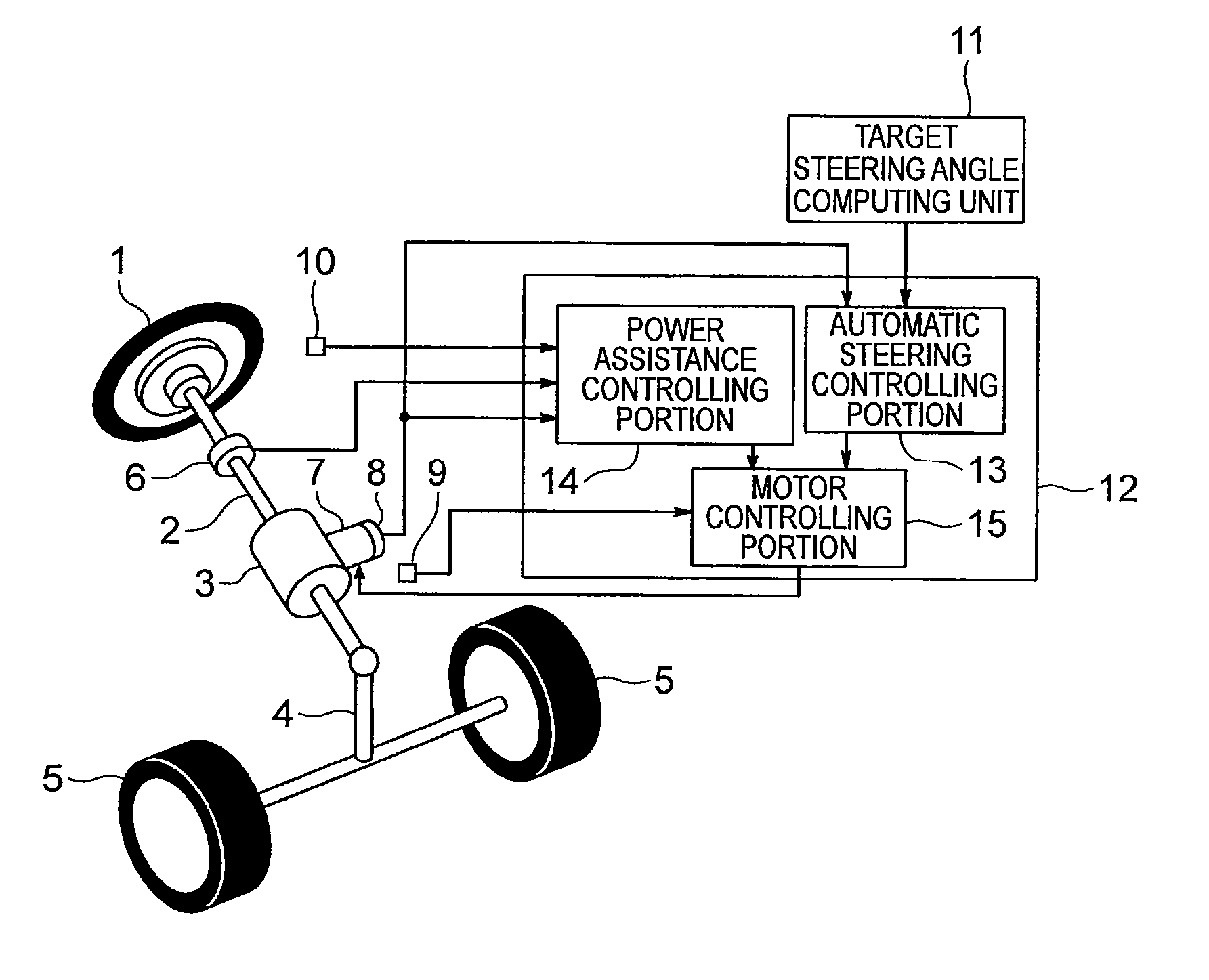
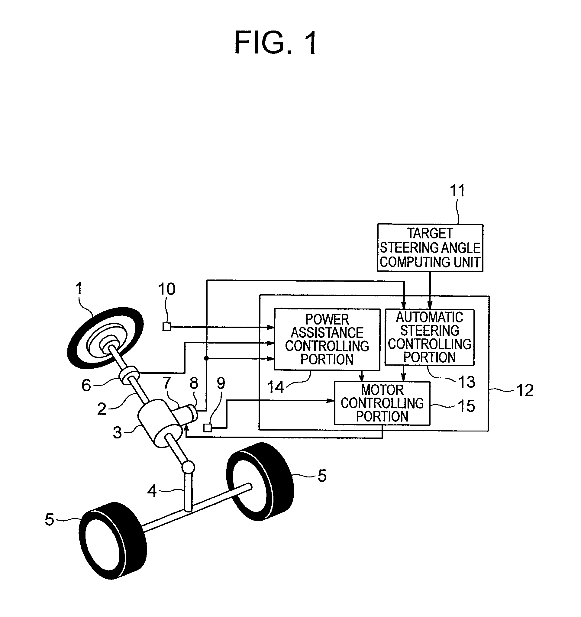
[0031]FIG. 1 is a configuration diagram that shows an automotive automatic steering apparatus according to Embodiment 1 of the present invention. In the figure, an end portion of a steering shaft 2 is linked to a steering wheel 1. The steering shaft 2 is rotated together with the steering wheel 1 so as to be centered around a shaft axis of the steering shaft 2. A steering mechanism portion4 is disposed on the steering shaft 2. A pair of left and right steered wheels 5 are disposed on the steering mechanism portion 4. The steering mechanism portion 4 steers the steered wheels 5 in response to rotation of the steering shaft 2. Specifically, the steering angles of the steered wheels 5 change in response to a rotational angle of the steering shaft 2.
[0032]A speed reducing apparatus 3 and a torque sensor (a torque detecting portion) 6 are disposed on intermediate portions of the steering shaft 2. The torque sensor 6 is disposed on a portion of the steering shaft 2 between the speed reduc...
embodiment 2
[0067]FIG. 8 is a block diagram that shows a control unit 12 of an automotive automatic steering apparatus according to Embodiment 2 of the present invention. In the figure, an automatic steering controlling portion 13 has a vibration suppressor 21 and an adder 22 in addition to a motor angular acceleration limiter 16 and an angle controller 17.
[0068]The vibration suppressor 21 calculates a vibration suppressing electric current that corresponds to steering torque to which a steering shaft 2 is subjected based on information from a torque sensor 6. Specifically, the vibration suppressor 21 calculates the vibration suppressing electric current by applying gain to the steering torque that is detected by the torque sensor 6.
[0069]The adder 22 adds the vibration suppressing electric current that is calculated by the vibration suppressor 21 to an angle controlling electric current that is calculated by the angle controller 17, and sets the sum of the angle controlling electric current an...
embodiment 3
[0071]FIG. 9 is a configuration diagram that shows an automotive automatic steering apparatus according to Embodiment 3 of the present invention. In this example, a torque sensor 6 is not disposed on a steering shaft 2. Consequently, no portion of the steering shaft 2 is a torsion bar. A steering wheel angle sensor 31 that generates a signal that corresponds to the rotational angle of a steering wheel 1 is disposed on the steering wheel 1. The respective information from the steering wheel angle sensor 31, an angle sensor 8, an electric current sensor 9, and a target steering angle computing unit 11 is sent to a control unit 12. In this example, information from a vehicle speed sensor 10 is not sent to the control unit 12. The control unit 12 does not have a power assistance controlling portion 14, but has an automatic steering controlling portion 13 and a motor controlling portion 15.
[0072]The automatic steering controlling portion 13 calculates an automatic steering target electri...
PUM
 Abstract
Description
Claims
Application Information