High Output Modular CAES (HOMC)

a modular caese and high output technology, applied in the field of electric power generation capacity, can solve problems such as substantial obstacles, blackouts, and increased local electrical power generation capacity through gas turbines

Active Publication Date: 2013-02-21
POWERPHASE
View PDF3 Cites 16 Cited by
  • Summary
  • Abstract
  • Description
  • Claims
  • Application Information

AI Technical Summary

Benefits of technology

[0010]One advantage of the present embodiment is the ability to construct the system on a mobile platform capable of being transported in whole or in pieces.

Problems solved by technology

For example, a sustained heat wave in New York City can erode that margin to the point that “brown-outs” occur, and if the supply of electric power cannot be increased, or demand outstrips the increased supply, “black-outs” can occur.
Unfortunately, in times of extreme demand, the transmission grid has a limited capacity to provide additional electric power to population centers such as New York City, and despite years of discussion and a general acceptance of the need to upgrade the transmission grid, if and when additional capacity will be added remains unclear.
Unfortunately, increasing local electrical power generation capacity by installing additional gas turbines to meet demand in times of severe anomalies faces substantial obstacles, the most obvious being cost.
Since this results in very high costs per megawatt hour of electrical power actually produced, power authorities are understandably hesitant to invest in additional peakers where they have other options.
Space is also an issue in population centers such as New York City, where real estate is at a premium.
Acquiring sufficient land to build a new power plant while accommodating nearby residential and business interests can delay construction of additional power generation capacity long past the date that additional capacity is needed.
Permitting requirements to achieve acceptable emissions levels can further delay construction of additional generating capacity, particularly in densely populated areas.
Faced with such cost, space and emissions obstacles, power authorities often resort to the use of existing, less efficient generating capacity.
Also, older gas turbines are generally not as efficient as newer ones, which translates to more waste heat being given off per megawatt hour being generated.
As a result, use of this generating capacity often produces higher emissions, of carbon monoxide and / or other pollutants such as NOx and ozone, per megawatt hour of power generated than their “base-load” counterparts, which can raise air quality concerns depending upon what time of day this generating capacity is operated.
Therefore, locations for use of the SmartCAES system are limited by local geological conditions.
The emissions of the CAES2 system are typically lower than those produced by the SmartCAES system due to incorporation of a gas turbine having a premix combustion system, and although the use of pipes for air storage 208 can allow the CAES2 system to be installed at locations that do not have existing caverns, the quantity of pipes needed by the CAES2 system increases the cost of installing a CAES2 system to the point that many power authorities may feel is prohibitive.

Method used


Image

  • High Output Modular CAES (HOMC)
  • High Output Modular CAES (HOMC)
  • High Output Modular CAES (HOMC)

Examples


embodiment 1

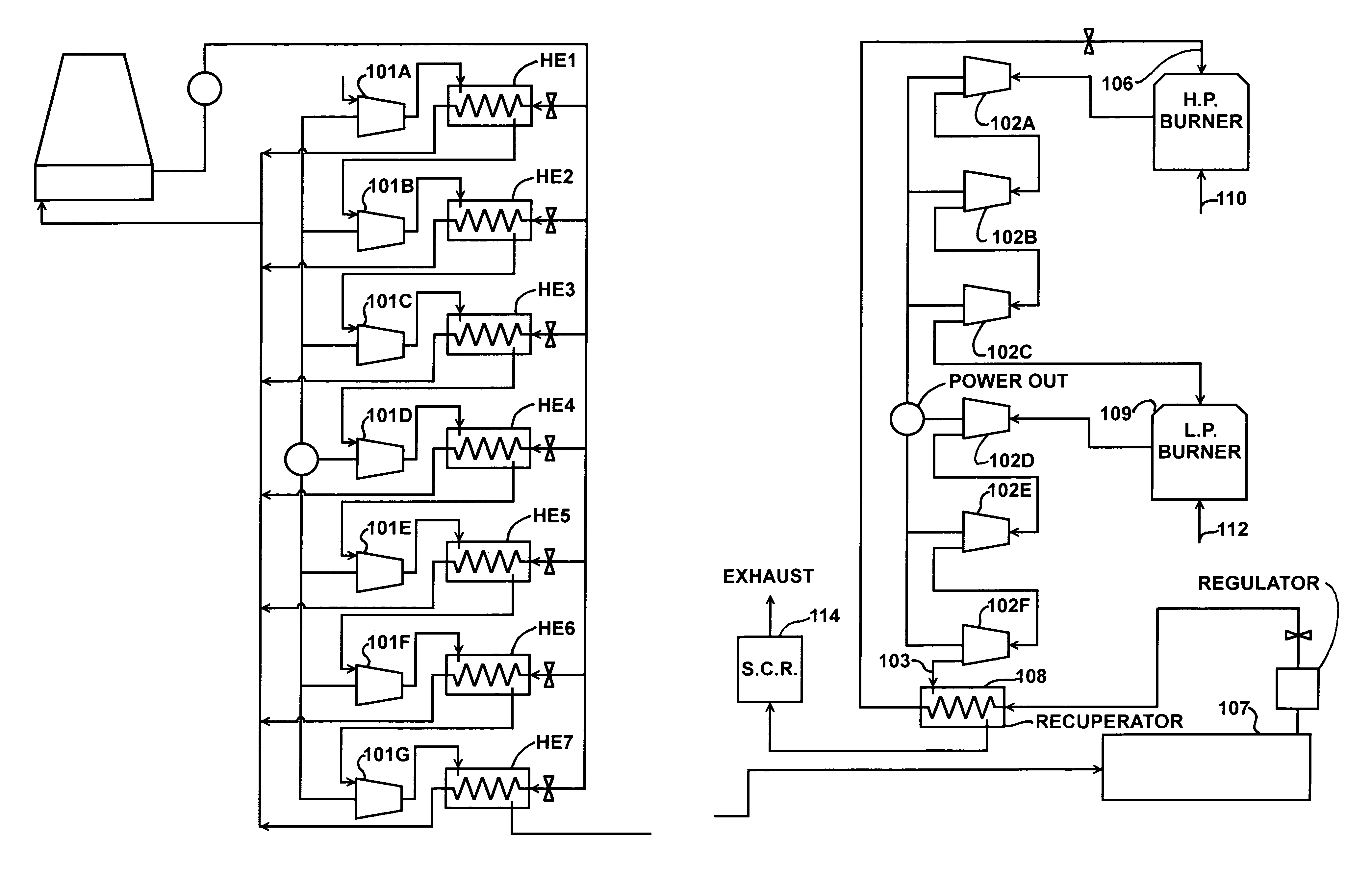
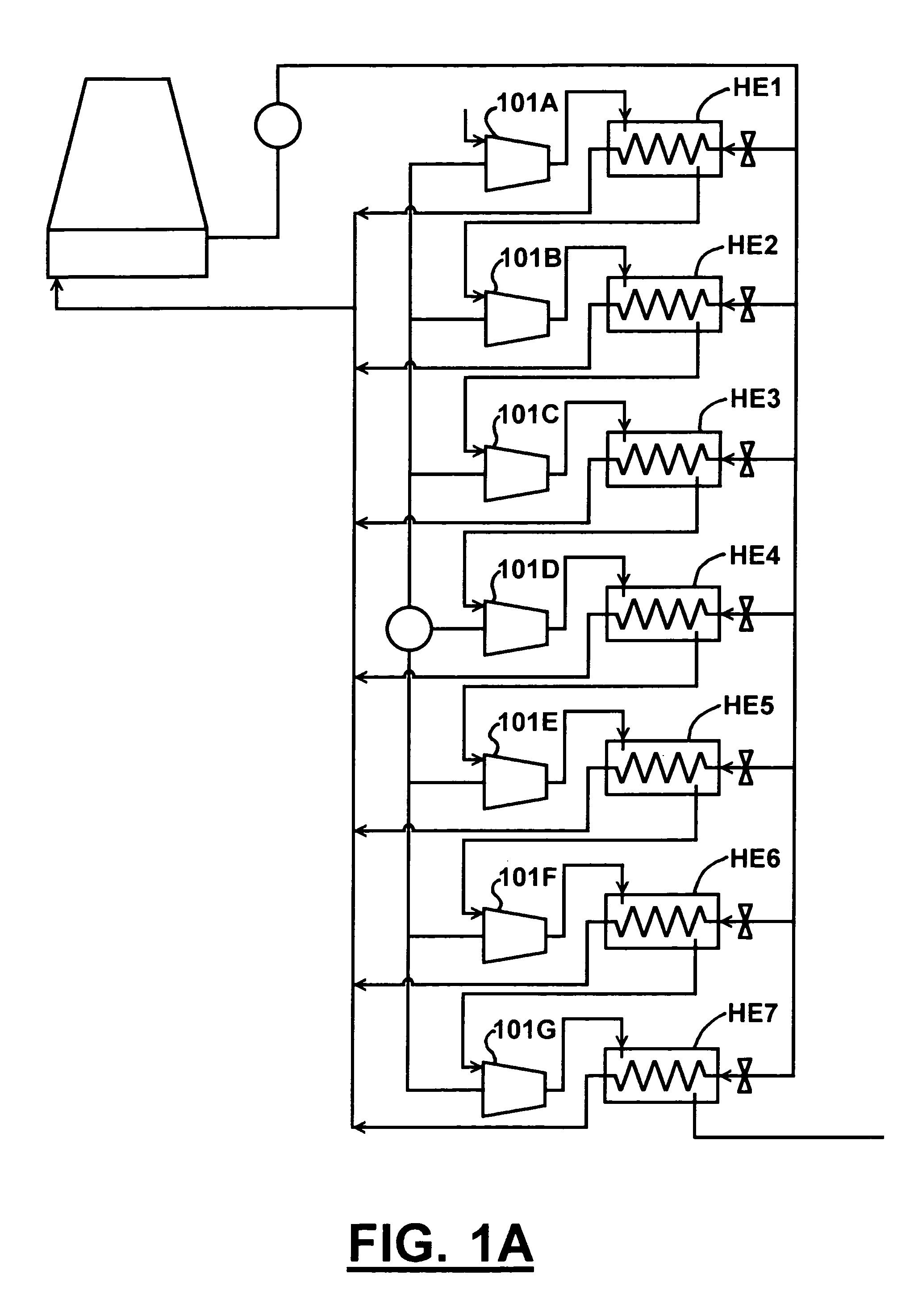
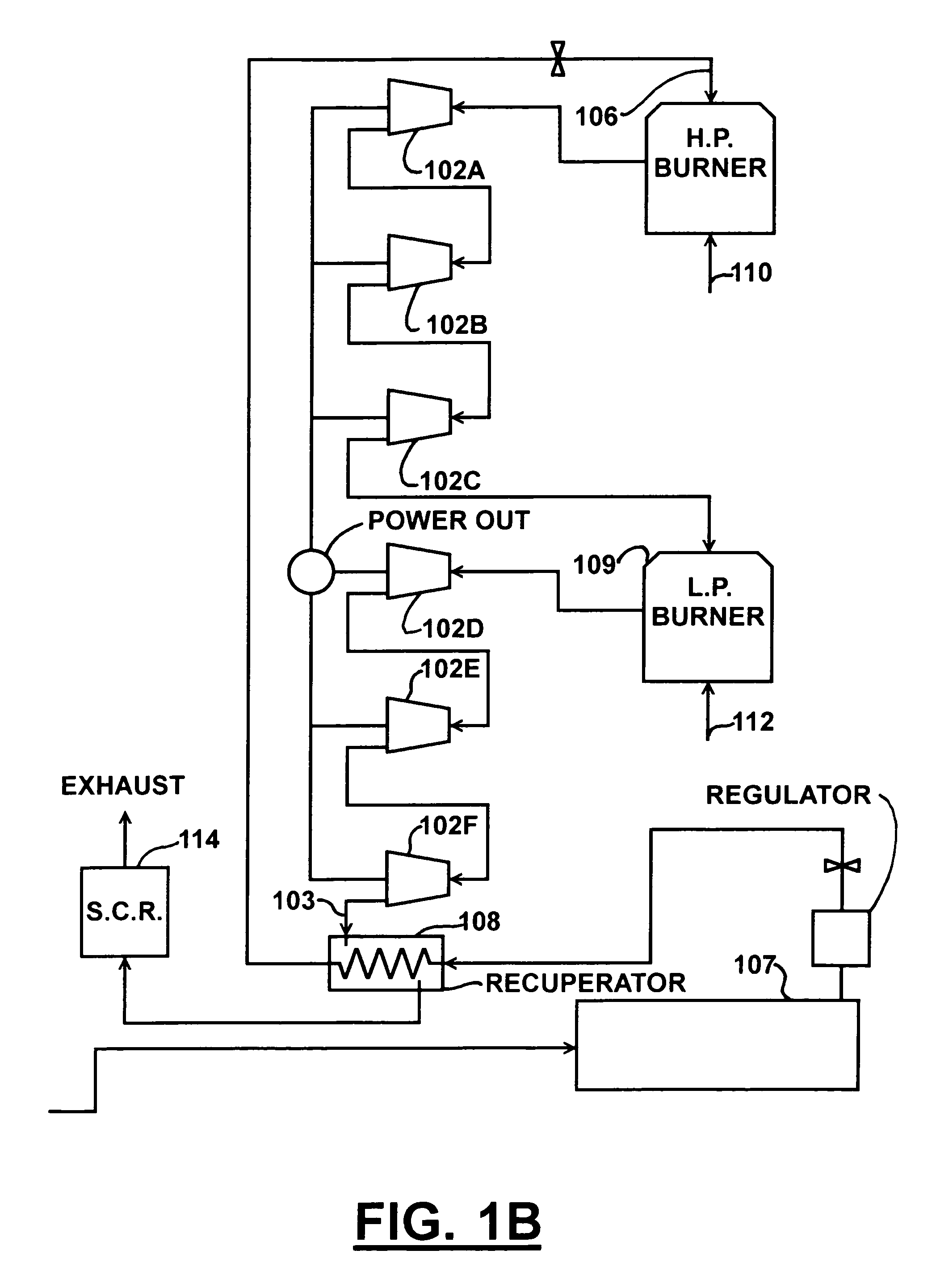
[0114]A second alternate embodiment of the present invention is shown in FIG. 5 which is similar to the first alternate embodiment, except that in this embodiment 1) the gas turbine exhaust is ducted to an exhaust-gas-to-air heat exchanger instead of an exhaust-gas-to-water heat exchanger, 2) the expansion circuit is decoupled from the heat exchangers 3HE1, 3HE2, 3HE3, 3HE4, 3HE5, 3HE6, 3HE7 used in the compression circuit such that the compression circuit has its own manifolds 347, 348 and heat exchangers 3HE1, 3HE2, 3HE3, 3HE4, 3HE5, 3HE6, 3HE7, and the expansion circuit has its own manifolds 550, 551 and six air-to-air heat exchangers 5HE8, 5HE9, 5HE10, 5HE11, 5HE12, 5HE13, and one pre-heater heat exchanger 319. Since the heat exchangers used in the compression circuit use a liquid coolant, they cannot double as heat exchangers for the expansion circuit due to the differences in the heat transfer medium used. Accordingly, a separate bank of air-to-air heat exchangers (5HE8, 5HE9,...

second embodiment

[0115]The compression circuit of the second alternate embodiment of the present invention is the same as described for the preferred embodiment, and, except for the changes described with respect to the heating of the hot water described in the first alternate embodiment, the heat transfer fluid supply circuit is also the same. Likewise, the expansion circuit of the second alternate embodiment of the present invention is similar to that described for the preferred embodiment, but in the second alternate embodiment of the present invention, the eighth heat exchanger 3HE8 replaces the sixth heat exchanger 3HE6, the ninth heat exchanger 3HE9 replaces the fifth heat exchanger 3HE5, the tenth heat exchanger 5HE10 replaces the fourth heat exchanger 3HE4, the eleventh heat exchanger 5HE11 replaces the third heat exchanger 3HE3, the twelfth heat exchanger 5HE12 replaces the second heat exchanger 3HE2, and the thirteenth heat exchanger 5HE13 replaces the first heat exchanger 3HE1. Other than...


PUM


Abstract

A compressed air energy storage system integrated with a source of secondary heat, such as a simple cycle gas turbine, to increase power production and to provide power regulation through the use of stored compressed air heated by said secondary heat to provide power augmentation.

Description

FIELD OF THE INVENTION[0001]This invention relates to electrical power generating capacity, and more specifically to energy storage that is useful for providing electrical power during periods of peak electrical power demand and power regulation.BACKGROUND OF THE INVENTION[0002]As demand for electric energy has risen in recent years, in some population centers such as New York City, the difference between the peak electric power that can be supplied and the peak demand for that electric power, referred to as “margin”, has narrowed to the point that a severe anomaly could eliminate that margin altogether. For example, a sustained heat wave in New York City can erode that margin to the point that “brown-outs” occur, and if the supply of electric power cannot be increased, or demand outstrips the increased supply, “black-outs” can occur. To reduce the risk of “brown-outs” and “black-outs”, responsible power authorities have tried to locate sufficient power generation capacity in or nea...

Claims


Application Information

Patent Timeline
Patent Type & Authority Applications(United States)
IPC IPC(8): F15B1/26
CPCH02J15/006Y02E60/15F15B1/022Y02E20/16F01K23/10F01K27/00F02C6/16Y02P90/50Y02E60/16
Inventor KRAFT, ROBERT J.
Owner POWERPHASE
Why Eureka
Try Eureka