Thermal energy management component and system incorporating the same

Inactive Publication Date: 2013-02-21
GENERAL ELECTRIC CO
View PDF10 Cites 13 Cited by
  • Summary
  • Abstract
  • Description
  • Claims
  • Application Information

AI Technical Summary

Problems solved by technology

However, as power distribution systems require higher operating current densities, increasing the power density through the busbars has challenges such as airflow and ventilation, vibration, noise, and efficient use of space.

Method used


Image

  • Thermal energy management component and system incorporating the same
  • Thermal energy management component and system incorporating the same
  • Thermal energy management component and system incorporating the same

Examples


Embodiment Construction

[0026]Example embodiments are described below in detail with reference to the accompanying drawings, where the same reference numerals denote the same parts throughout the drawings. Some of these embodiments may address the above and other needs.

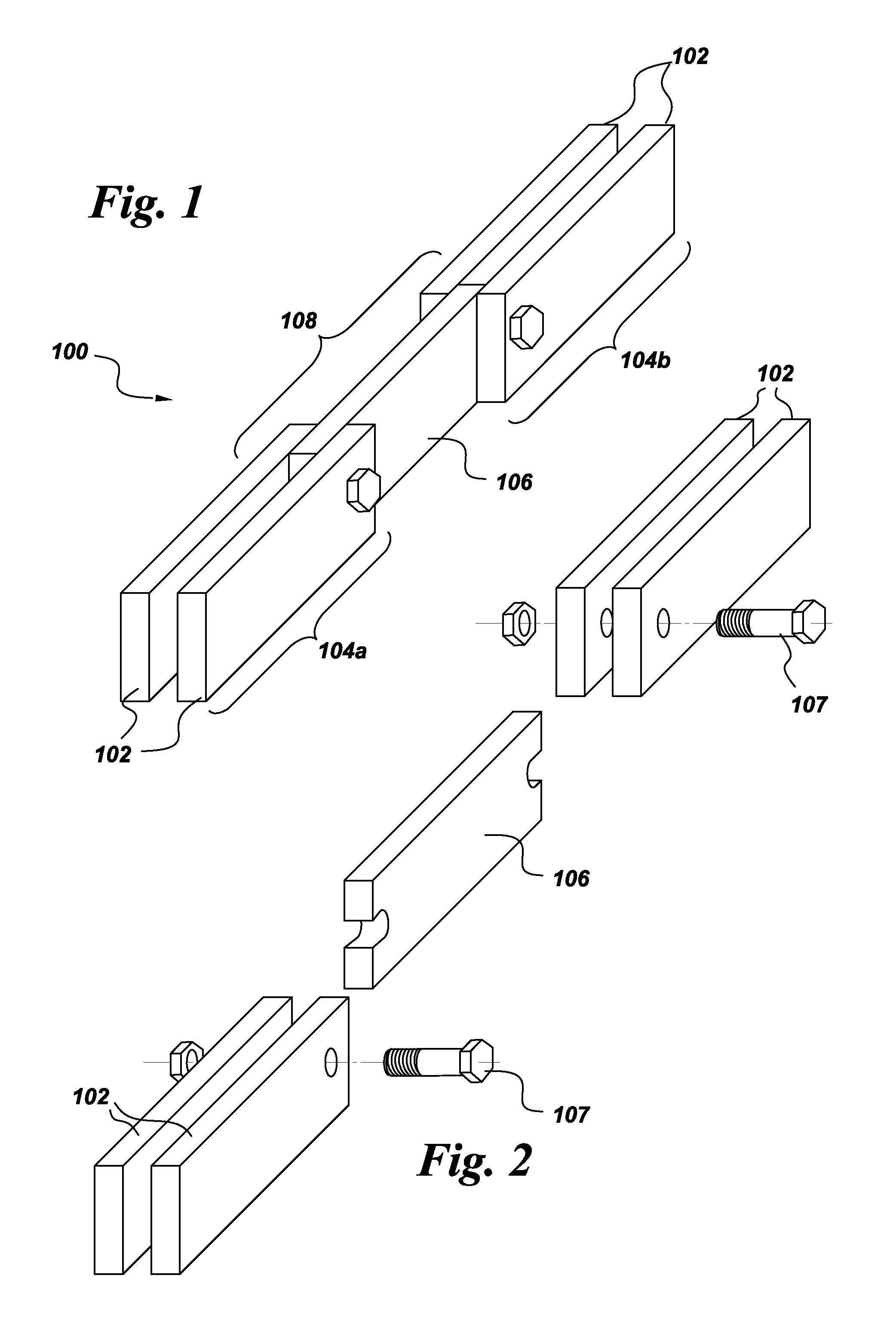
[0027]Referring to FIGS. 1 and 2, therein is shown an electrical component, such as, for example, a busbar 100. The busbar 100 can include a pair of opposing metal plates 102 that can serve to conduct electricity. The busbar 100 can include discrete busbar sections 104a, 104b. Adjacent busbar sections 104a, 104b can be mechanically and electrically coupled using a connector 106 (for example, in conjunction with bolts 107), thereby forming a busbar joint 108.

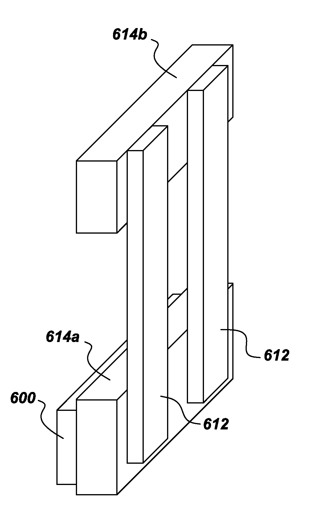
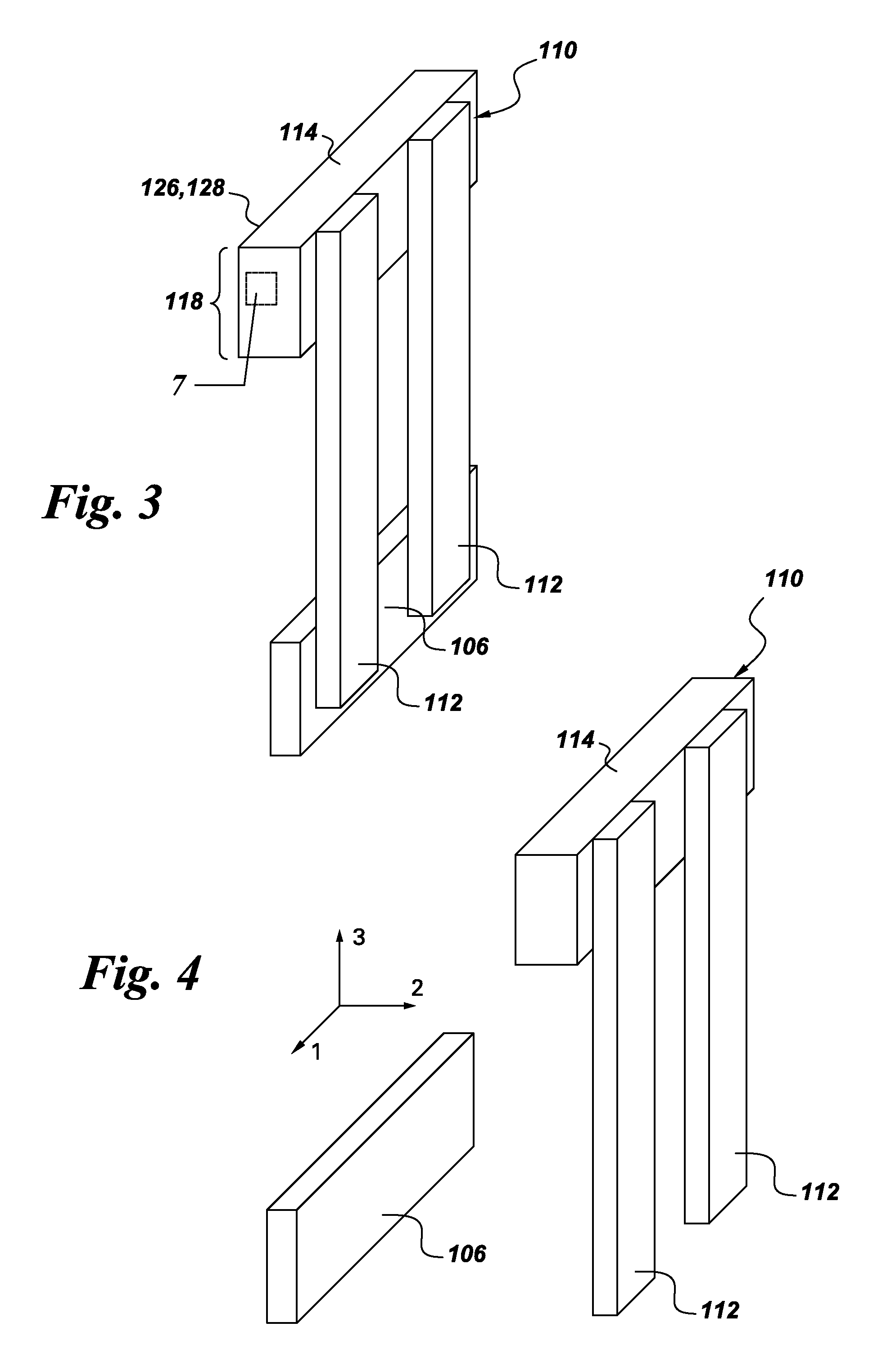
[0028]Referring to FIGS. 3-7, a thermal energy management component 110 can be configured to receive thermal energy from the busbar 100. For example, the thermal energy management component 110 can be configured to receive thermal energy from the busbar joint 108. The thermal energy manag...


PUM


Abstract

An apparatus is provided that includes a heat pipe and a heat sink that includes a foam (e.g., a metal foam, a carbon foam, and / or a graphite foam) and is configured to exchange thermal energy with the heat pipe. For example, the heat pipe can include a thermal energy receiving portion and a thermal energy rejecting portion. The heat sink can be configured to receive thermal energy from a busbar and the thermal energy receiving portion can be configured to receive thermal energy from said heat sink. Alternatively, the thermal energy receiving portion can be configured to receive thermal energy from a busbar, and the heat sink can be configured to receive thermal energy from the thermal energy rejecting portion.

Description

BACKGROUND[0001]The subject matter disclosed herein generally relates to thermal management and particularly to thermal management of busbars.[0002]Power distribution in a high current environment requires current flow from a power supply to various components, for example, drive systems, motors, electrical loads, amplifiers, rectifiers, routers, servers, etc. Among the more common methods used to supply power are heavy gauge wire and cable, switchgears, circuit boards, and busbars.[0003]Typically, power distribution has involved one or more heavy copper busbars that are provided with connectors or holes for connecting cables. Busbars might be spaced apart from each other and isolated by insulating spacers. Large copper or aluminum busbars and cables have been used to distribute power within industrial control systems. Such busbars are large and can carry high power relatively easily. Traditionally, busbars cooling techniques involved circulating air within a cabinet to cool the bus...

Claims


Application Information

Patent Timeline
Patent Type & Authority Applications(United States)
IPC IPC(8): H02G5/10
CPCH02G5/10
Inventor SUBRAMANIAM, PRADIP RADHAKRISHNANASOKAN, THANGAVELUREDDY, SUDHAKAR EDDULADHAR, SANDEEP
Owner GENERAL ELECTRIC CO
Why Eureka
Try Eureka