High capacity lithium ion battery formation protocol and corresponding batteries

a lithium ion battery, high capacity technology, applied in the direction of secondary cell servicing/maintenance, non-aqueous electrolyte cells, cell components, etc., can solve the problem that the performance of secondary lithium ion batteries generally decreases with increasing the cycle number

Active Publication Date: 2013-02-21
IONBLOX INC
View PDF2 Cites 60 Cited by
  • Summary
  • Abstract
  • Description
  • Claims
  • Application Information

AI Technical Summary

Benefits of technology

[0010]In a fifth aspect, the invention pertains to a lithium ion battery that comprises a positive electrode comprising an active material, a negative electrode, a separator between the positive electrode and negative electrode, and an electrolyte comprising lithium ions. The positive electrode active material comprises a lithium rich metal oxide that can be approximately represented by the formula Li1+bNiαMnβCoγAδO2−zFz, where b ranges from about 0.01 to about 0.3, α ranges from 0 to about 0.4, β range from about 0.2 to about 0.65, γ ranges from about 0 to about 0.46, δ ranges from about 0.001 to about 0.15, and z ranges from 0 to about 0.2 with the proviso that both α and γ are not zero, and where A is a metal different from Ni, Mn and Co or a combination thereof. The positive electrode active material of the battery can have a discharge specific capacity at a rate of C / 3 from 4.35V to 2.5V at the 5th discharge cycle that is at least about 160 mAh / g and having a calendar life at an 85% state of charge at 30 degrees C. of at least about 2 years based on discharge capacity decay of no more than about 20%. In some embodiments, the positive electrode active material of the battery can have a calendar life at 30 degree C. of at least about 3 years based on discharge capacity decay of no more than about 20%. In some embodiments, the lithium rich metal oxide of the battery can be approximately represented by x Li2MnO3.(1−x) LiNiuMnvCowAyO2, wherein z=0 and the stoichiometry defines x, u, v, w and y in terms of b, α, β, γ and δ, and wherein 0.125≦x≦0.325. The negative electrode of the battery can comprise graphitic carbon.

Problems solved by technology

With cycling, however, secondary lithium ion batteries generally have decreased performance with increased cycle number.

Method used


Image

  • High capacity lithium ion battery formation protocol and corresponding batteries
  • High capacity lithium ion battery formation protocol and corresponding batteries
  • High capacity lithium ion battery formation protocol and corresponding batteries

Examples


example 1

Synthesis of Cathode Materials and Corresponding Electrodes and Batteries

[0111]High capacity cathode materials represented by formula x Li2MnO3.(1−x) LiNiuMnvCowMgyO2, were synthesized using a procedure disclosed in published U.S. patent application 2010 / 0086853A (the '853 application) to Venkatachalam et al. entitled “Positive Electrode Material for Lithium Ion Batteries Having a High Specific Discharge Capacity and Processes for the Synthesis of these Materials”, and published U.S. patent application 2010 / 0151332A (the '332 application) to Lopez et al. entitled “Positive Electrode Materials for High Discharge Capacity Lithium Ion Batteries”, both incorporated herein by reference. The stoichiometry of cathode materials having compositions 1-2 are outlined in Table 1 below.

TABLE 1Mn (% transitionCompositionXMgmetals)10.17500.4520.30.010.51

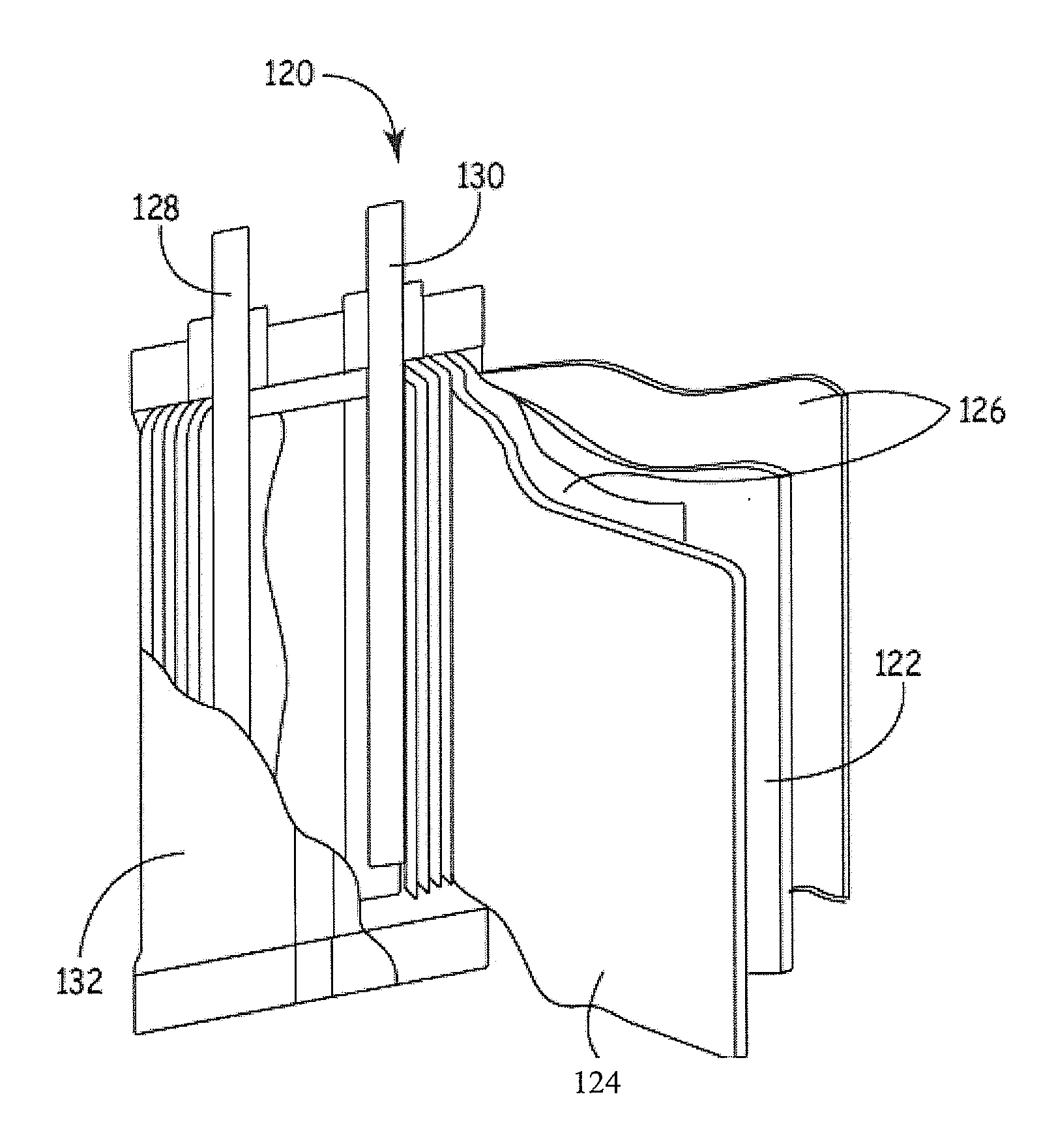
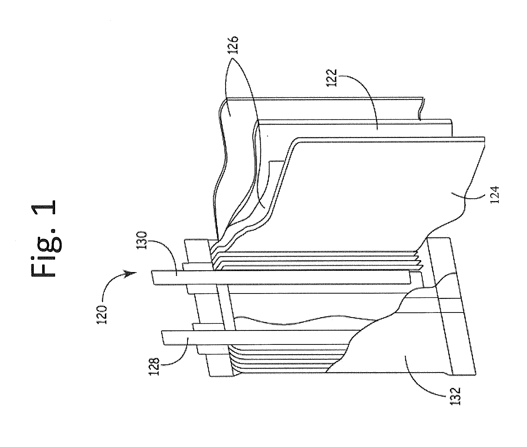
[0112]Compositions 1 to 2 were then used to construct corresponding positive electrodes, which were in turn used to construct corresponding sets o...

example 2

Evaluation of Battery Performance Under Different Formation Protocols

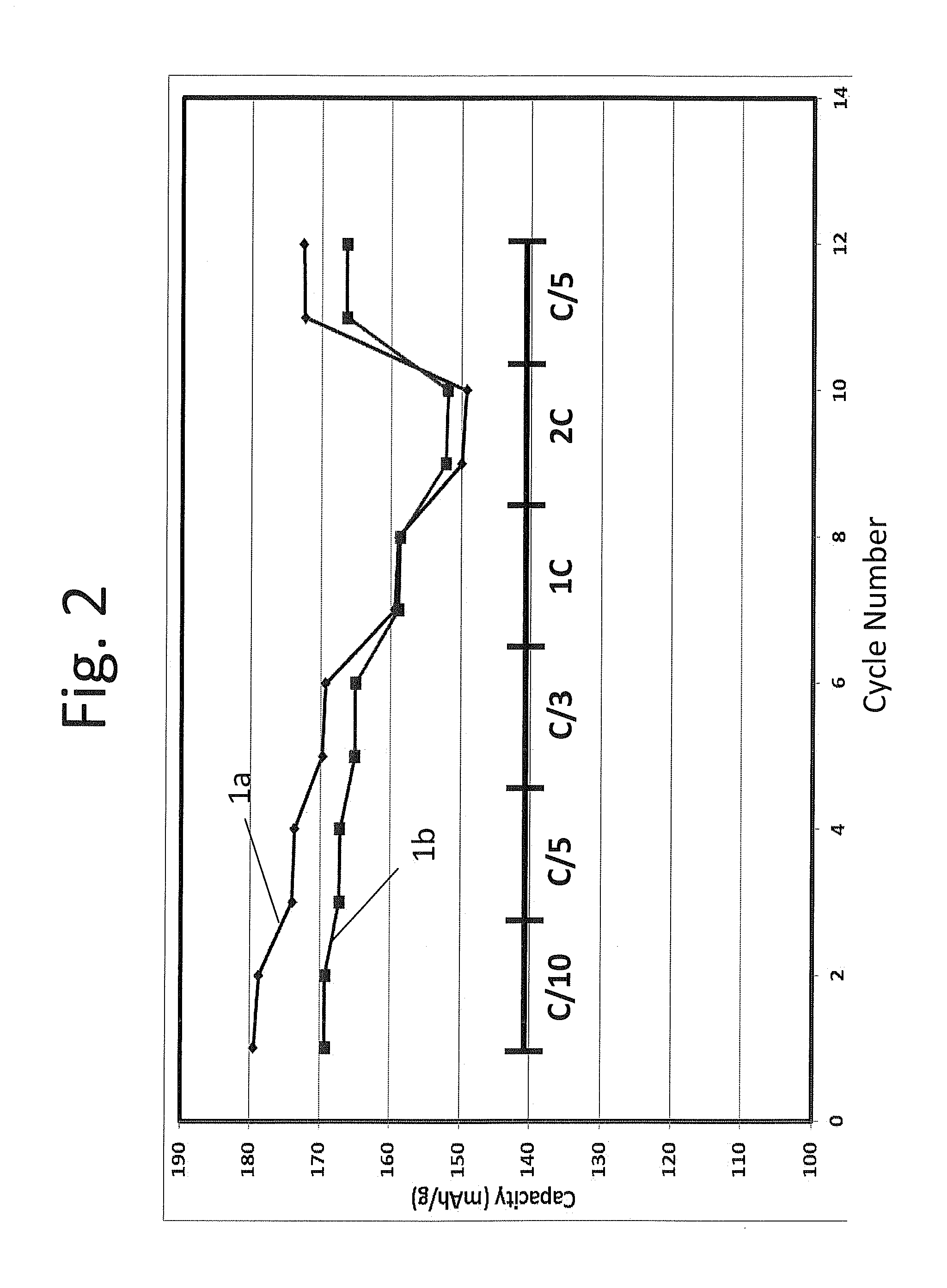
[0114]Coin cell batteries 1a and 1b formed from composition 1 of example 1 and a graphitic carbon counter electrode were activated under formation protocols 1 and 2 of table 2 above, respectively, i.e. battery 1a was activated at 4.6V and battery 1b was activated at 4.35V. The batteries were cycled at a rate of C / 10 for the 1st and 2nd cycles, at a rate of C / 5 for the 3rd and 4th cycles, at a rate of C / 3 for the 5th and 6th cycles, at 1 C for cycles 7th and 8th, at 2 C for cycles 9th and 10th, and at C / 5 for cycles 11th and 12th, respectively between 4.35-2.5V and the results are plotted in FIG. 2. As shown in FIG. 2, battery 1a activated under formation protocol 1 had higher specific capacity than battery 1b activated under formation protocol 2, except for at rate 2 C. Thus, surprisingly, the battery with only partial activation actually exhibited a greater specific capacity than the battery with full activation a...

example 3

Evaluation of Batteries Based on Differential Capacity Plots

[0115]Coin cell batteries 1c, 1d, 1e, and 1f formed from composition 1 of example 1 and graphitic carbon counter electrode were activated at 4.25V, 4.30V, 4.35V, and 4.5V respectively and tested for differential capacity. The results of differential capacity versus voltage are plotted in FIG. 3. As shown in FIG. 3, especially the enlarged portions 3A and 3B, manganese activity is suppressed when the batteries are cycled up to 4.35V (1e). However, when higher voltage such as 4.5V (1f) are used, there is an increase in Mn activity.

[0116]Coin cell batteries 1g, 1h, and 1j formed from composition 1 of example 1 and lithium foil counter electrode were activated using different formation protocol and procedures and tested for differential capacity. The results of differential capacity versus voltage are plotted in FIG. 4. Specifically, for battery 1g, the battery was charged to 4.4 V in the first cycle and discharged to 2.0 volts...


PUM

PropertyMeasurementUnit
voltageaaaaaaaaaa
voltageaaaaaaaaaa
voltageaaaaaaaaaa

Abstract

Battery formation protocols are used to perform initial charging of batteries with lithium rich high capacity positive electrode to result a more stable battery structure. The formation protocol generally comprises three steps, an initial charge step, a rest period under an open circuit and a subsequent charge step to a selected partial activation voltage. The subsequent or second charge voltage is selected to provide for a desired degree of partial activation of the positive electrode active material to achieve a desired specific capacity while providing for excellent stability with cycling. The formation protocol is particularly effective to stabilize cycling for compositions with moderate lithium enrichment.

Description

CROSS REFERENCE TO RELATED APPLICATIONS[0001]This application is a continuation-in-part of copending U.S. patent application Ser. No. 13 / 213,756 filed on Aug. 19, 2011 (published application 2012 / 0056590, hereinafter the '590 application) to Amiruddin et al., entitled “Very Long Cycling of Lithium Ion Batteries With Lithium Rich Cathode Materials,” incorporated herein by reference.FIELD OF THE INVENTION[0002]The invention relates to initial charging for formation of lithium ion batteries with high specific capacity positive electrode active materials. The invention further relates to batteries formed using an improved formation protocol.BACKGROUND OF THE INVENTION[0003]Rechargeable lithium ion batteries, also known as secondary lithium ion batteries are desirable as power sources for a wide range of applications. Their desirability stems from their relative high energy density. The capacities of secondary lithium ion batteries have been greatly improved with the development of high ...

Claims


Application Information

Patent Timeline
Patent Type & Authority Applications(United States)
IPC IPC(8): H01M4/525H02J7/00H01M4/583H01M10/056H01M4/54H01M4/485
CPCH01M4/131H01M4/362H01M4/505H01M4/525Y02E60/122H01M10/0525H01M10/056H01M10/44H01M4/587Y02E60/10H01M4/0447
Inventor AMIRUDDIN, SHABABLI, BING
Owner IONBLOX INC
Why Eureka
Try Eureka