
Method of removing phosphorus from wastewater

a technology of wastewater and phosphorus, which is applied in water/sewage treatment by ion exchange, quaries waste water treatment, separation processes, etc., can solve the problems of no longer being able to remove more phosphorus from solution, sludge will become saturated with phosphorus, etc., and achieve the effect of reducing the overall phosphorus load

Active Publication Date: 2007-11-13
U S A AS REPRESENTED BY THE SEC OF THE DEPT OF THE INTERIOR
View PDF16 Cites 19 Cited by
  • Summary
  • Abstract
  • Description
  • Claims
  • Application Information

AI Technical Summary

Benefits of technology

[0011]The invention proposed herein comprises a method of and system for removing phosphorus or other elements from wastewater streams, particularly from high volume wastewater streams having low concentrations of phosphorus, arsenic, selenium or other like elements, such as streams from animal feeding operations. The invention uses low-cost materials and can significantly reduce the overall phosphorus load provided by agricultural operations to open waters
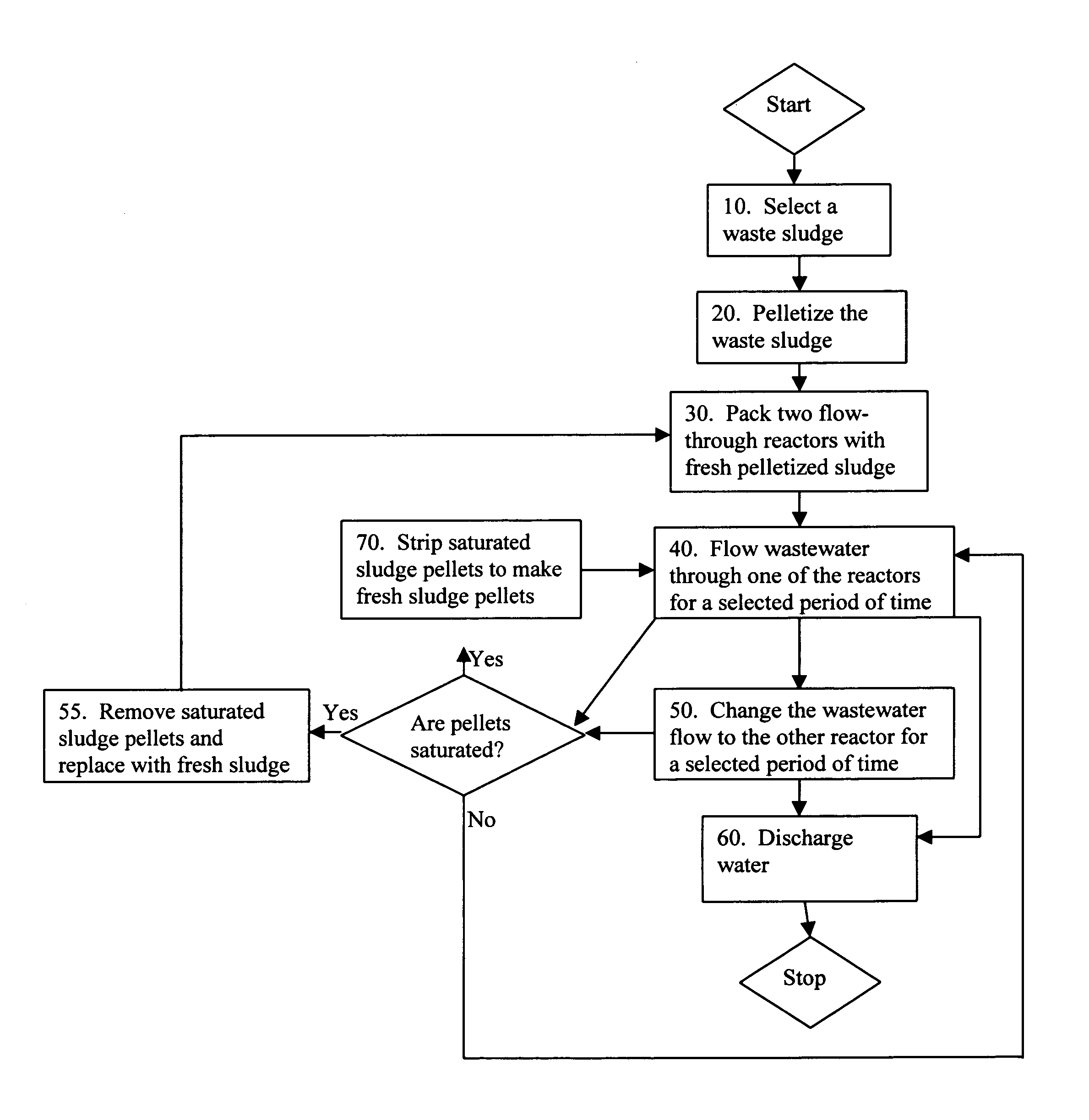
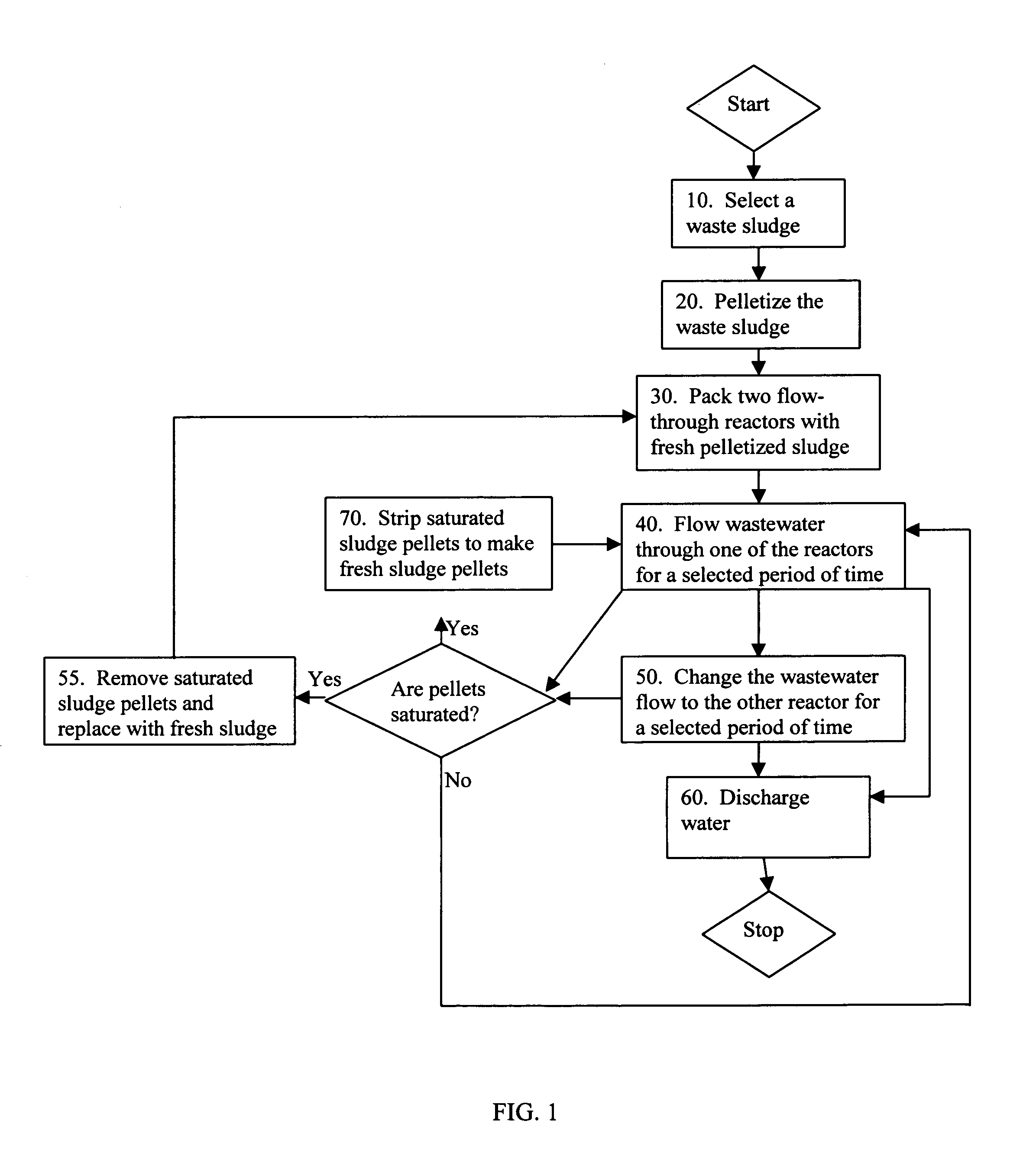
[0012]Accordingly, it is an object of this invention to provide a method of removing phosphorus or other elements from wastewater streams that is low-cost compared to current removal methods.
[0013]It is a further object of this invention to provide a method of removing phosphorus or other elements from wastewater streams that can be easily incorporated into high volume streams with low concentrations of phosphorus or other elements, such as fish hatcheries.
[0014]This invention meets these and other objectives related to removal of phosphorous or other elements from wastewater by providing a method of and system for removing phosphorus from wastewater using a waste sludge that has a high affinity for phosphorus or other selected elements. So the waste sludge can be used in a flow-through contact reactor to remove the phosphorus from a wastewater stream, the waste sludge is pelletized. The waste sludge pellets are packed into one or more flow-through contact reactors. In the configuration described herein, phosphorus adsorption capacity is maximized by flowing the wastewater through the reactor(s) in a “pulsed” manner, rather than continuously in one reactor. In order to treat water continuously, a pair of columns is required, with flow alternating between the columns, which are switched at regular intervals. The adsorption capacity of the sludge is increased tremendously by using these alternating flow and rest periods. Eventually, however, the sludge will become saturated with phosphorus and will no longer be able to remove more phosphorus from solution. At this point, the sludge would be either stripped and rinsed for reuse or replaced by a fresh batch. Stripping can be accomplished by contacting the sludge with an alkaline solution, preferably at pH of about 13, such as 0.1 molar solution of sodium hydroxide or some other strong base. The strip procedure is conducted at a lower rate of flow to increase the concentration of phosphorus in the strip solution and conserve chemical reagent.

Problems solved by technology

Eventually, however, the sludge will become saturated with phosphorus and will no longer be able to remove more phosphorus from solution.

Method used


Image

  • Method of removing phosphorus from wastewater
  • Method of removing phosphorus from wastewater
  • Method of removing phosphorus from wastewater

Examples


example 1

[0049]A sample of sludge “A” was packed in a glass chromatography column with an internal diameter of 1.5 cm and a height of 50 cm. Dried sludge particles from source “A” were screened to 5×10 mesh size and 36.7 g sludge was added to the column. Water was pumped through the column in a downward direction at a rate of 15 ml / min, using a Masterflex peristaltic pump. The water was a synthetic wastewater composed of spring water from the Leetown Science. Center to which KH2PO4 had been added to give a total phosphorus concentration of 1 mg / L. Performance of such columns is typically quantified by the time and volume of solution treated before a specified fraction of absorbate is detected in the column effluent. Scale up is done on the basis of the cross sectional area of the column, so results are typically expressed as time before breakthrough at a given flow rate in gallons per minute per square foot of column area. Under the conditions specified above, the area-based flow rate was 2....

example 2

[0050]A similar test was conducted using a second sludge sample (hereinafter, sludge “B”). The same equipment, configuration, and flow used in EXAMPLE 1 above were employed. However, rather than the “pulsed” flow used in EXAMPLE 1, the water was flowed continuously through the packed column. Results are also shown in FIG. 5. Phosphorus removal was much less effective than in EXAMPLE 1. Although this could be due to the effect of different sludge type, results from the kinetic test discussed earlier indicated that sludge “B” still has a good affinity for phosphorus, and indicated that “resting” of the column in the first test provided superior performance.

example 3

[0051]AMD sludge pellets with a binder of 30% Portland cement were loaded into a pair of transparent plastic columns. Simulated wastewater was pumped through the column with a peristaltic pump. Flow was switched between columns on a 12-hour cycle. Results for this pelletized batch of AMD solids is shown in FIG. 6. Here, the columns treated a flow of 2.1 gpm / ft2 for over 30 days with a phosphorus recovery of 60% of the incoming P, again, at a very low initial concentration.


PUM

PropertyMeasurementUnit
diameteraaaaaaaaaa
timeaaaaaaaaaa
timeaaaaaaaaaa

Abstract

A method of and system for removing phosphorus from wastewater using a waste sludge that has a high affinity for phosphorus. So the waste sludge can be used in a flow-through contact reactor to remove the phosphorus from a wastewater stream, the waste sludge is pelletized. The waste sludge pellets are packed into one or more flow-through contact reactors. In the configuration described herein, phosphorus removal is maximized by flowing the wastewater through the reactor(s) in a “pulsed” manner, rather than continuously. Thus, wastewater is flowed through the reactor(s) for a period of time and stopped for a period of time. By giving the sludge absorbent a rest period, the absorption capacity of the sludge is increased significantly, thus decreasing the frequency of regeneration or replacement of the sludge. Sludge regeneration can be accomplished with a stripping step using an alkaline solution of pH 13, followed by rinsing with water.

Description

STATEMENT OF GOVERNMENT INTEREST[0001]The invention described herein may be manufactured and used by or for the Government of the United States of America for governmental purposes without payment of any royalties thereon or therefor.BACKGROUND OF THE INVENTION[0002]1. Field of the Invention[0003]This invention relates in general to removal of phosphorus or other elements from wastewater, more particularly to removal of phosphorus from wastewater using waste sludge, and most particularly to removal of phosphorus from wastewater using waste sludge in a flow-through contactor.[0004]2. Description of the Related Art[0005]Excess phosphorus in runoff and wastewaters from animal production facilities can result in eutrophication of watersheds with serious consequences for aquatic life and water quality. One of the largest remaining phosphorus sources is agriculture, through overuse of fertilizers and disposal of animal wastes. As an example, like any animal feeding operation, fish hatcher...

Claims


Application Information

Patent Timeline
Patent Type & Authority Patents(United States)
IPC IPC(8): C02F1/42
CPCB01J20/06B01J20/28042C02F1/281B01J20/08Y10S210/906B01J2220/4887C02F11/008C02F2101/103C02F2101/105C02F2103/001C02F2103/10C02F2103/20C02F2209/44C02F2303/16Y10S210/912
Inventor SIBRELL, PHILIP L.
Owner U S A AS REPRESENTED BY THE SEC OF THE DEPT OF THE INTERIOR
Learn More