Wireless method and apparatus for detecting damage in ceramic body armor

Inactive Publication Date: 2013-02-21
CYNETIC DESIGNS
View PDF2 Cites 26 Cited by
  • Summary
  • Abstract
  • Description
  • Claims
  • Application Information

AI Technical Summary

Benefits of technology

[0009]In a first embodiment, the invention allows non-contact inspection of body armor plates without the use of wires or connectors. It employs the varying effect on resonant frequency caused by mutual induction bet

Problems solved by technology

A recurring issue for ballistic protection ceramic body armor plates such as the SAPI (Small Arms Protective Insert) and ESAPI (Enhanced Small Arms Protective Insert) and other configurations of body armor with a ceramic strike face, is that it is very difficult to determine the integrity of the ceramic plate when they are in service.
When plates are in service and especially when in theatre they are subject to the rigours of the battlefield.
As a result of their weight, the plates are repeatedly banged and struck against hard objects.
Even through such simple activities as when the vest is taken off and put down on the ground the ceramic may be damaged.
All these layers and covers make it impossible to determine the integrity of the ceramic and whether or not the plate should stay in service when the plate is inspected visually.
In addition several of these techniques cannot be used when a plate has any type of protective cover on it as the ceramic component needs to be directly accessed.
Even small digital x-ray testing capability however is not typically found in theatre and definitely not at forward operating bases where the hard armor is placed into daily active service to protect the soldie

Method used


Image

  • Wireless method and apparatus for detecting damage in ceramic body armor
  • Wireless method and apparatus for detecting damage in ceramic body armor
  • Wireless method and apparatus for detecting damage in ceramic body armor

Examples


Embodiment Construction

[0064]Soft armor vests for both soldiers and tactical police usually are designed with large front and rear pockets into which hard armor plates can be inserted. Hard armor plates are the heaviest part of a personal or body armor system and can weigh as much as 4.5 kgs each. Significant research has been undertaken to reduce the weight of the plates whilst also improving the ballistic protective performance as the hard armor is one of the soldiers heaviest single weight burdens.

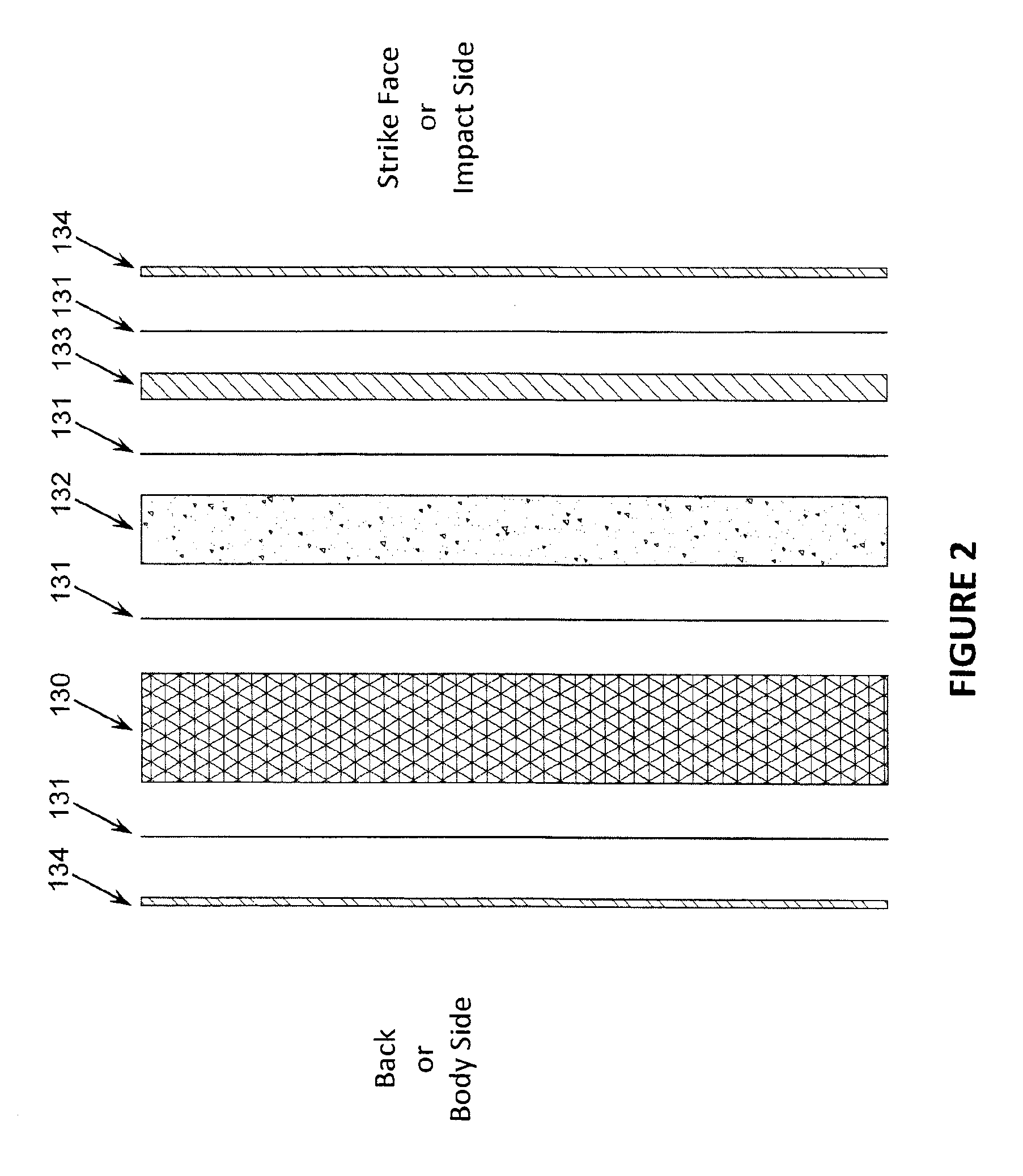
[0065]Hard armor plate construction falls into two principle groups; plates constructed with a ceramic strike face and adhered to a composite support backing, or plates that use no ceramic for the strike face and are made only of composite, such as an Ultra High Molecular Weight Plastic or a high tenacity fiber and resin.

[0066]For hard armor plates that employ a ceramic strike face, the ceramic is usually a sintered monolithic ceramic plate that is bonded to a backing of composite material. The strike face ce...


PUM

PropertyMeasurementUnit
Flow rateaaaaaaaaaa
Electrical inductanceaaaaaaaaaa
Frequencyaaaaaaaaaa

Abstract

A wireless damage detector for ceramic armor plates includes an interrogator and a body armor ceramic plate. The interrogator includes an inductive primary coil having a resonant frequency. The plate includes a corresponding inductive secondary coil adapted to cooperate with the primary coil when the interrogator is positioned in an interrogation position wirelessly adjacent the plate. When in the interrogation position, the primary and secondary coils are inductively coupled, that is, form an inductive coupling, when the primary coil is energized at the resonant frequency. The plate includes at least one self-contained frangible continuity circuit electrically connected to the secondary coil. The inductive coupling induces an electrical current flow in the continuity circuit when the circuit is undamaged. A detector cooperates with the primary and secondary coils when the interrogator is in the interrogation position. The detector detects the inductive coupling. An indicator cooperates with the detector.

Description

FIELD OF THE INVENTION[0001]The invention relates to personal ceramic / composite armor systems and a method to determine the integrity of the ceramic plate component while in the battlefield environment using rugged non-contact inspection equipment that does not require formal training to operate. The equipment allows non-contact inspection of body armor plates without the use of wires or connectors and is to be used as a field tool to pre-screen plates to determine if the plate should be sent for more involved inspection using x-ray equipment.BACKGROUND OF THE INVENTION[0002]The modern soldier is equipped with an ensemble of protective clothing. Part of the ensemble is ballistic protection which is typically comprised of a soft ballistic vest that provides fragmentation and hand gun protection. The ballistic vest has large plate pockets on the front and rear into which can be inserted hard armor plates that protect against high velocity ballistic threats. A recurring issue for balli...

Claims


Application Information

Patent Timeline
IPC IPC(8): G01R27/28
CPCF41H1/02F41H5/0428G01N27/023F41J5/14F41J5/04
Inventor SOAR, ROGER J.
Owner CYNETIC DESIGNS
Why Eureka
Try Eureka