Sensor having damping

Active Publication Date: 2013-02-21
ROBERT BOSCH GMBH
View PDF21 Cites 4 Cited by
  • Summary
  • Abstract
  • Description
  • Claims
  • Application Information

AI Technical Summary

Benefits of technology

The patent is about a sensor device that uses a flexible printed circuit board to connect to other components. This allows for a space-saving design and better resistance to falls and jolts. The flexible printed circuit board has a U-shaped form and can carry various chips securely. The method also allows for decoupling the chip structure and the application of the damper element, making processing easier. Overall, the patent provides a solution for producing a compact, damped sensor device with improved safety and flexibility.

Problems solved by technology

In the conventional sensor device, there may be the problem that the damping is effective only at certain frequencies, whereby vibrations are able to lead to interferences of the sensor chip and with that, of the measuring signals.
Besides the required elasticity, however, the damper element is subject to further requirements, so that selection of the material is greatly restricted.
For the decoupling of various interference frequencies, it may be required for each case to have its own housing, which is connected with high expenditure.
Furthermore, the construction of the sensor device may lead to the impairment or interruption of the electrical connection.
Jolts or accelerations, which may occur, for instance, during a drop test or improper handling of the sensor device, result in a relatively great deflection of the base plate with respect to the housing frame.
The essentially horizontal construction of the sensor device also has a relatively great lateral requirement for space.
In this way, chips that are not in a housing are able to be reliably situated or carried on the fastening section of the printed circuit board.

Method used


Image

  • Sensor having damping
  • Sensor having damping
  • Sensor having damping

Examples


Embodiment Construction

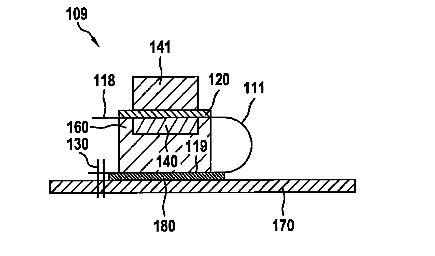
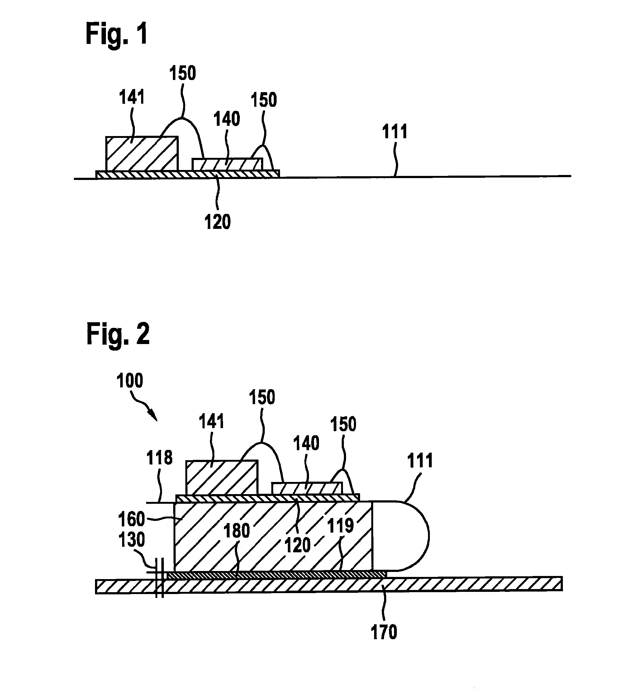
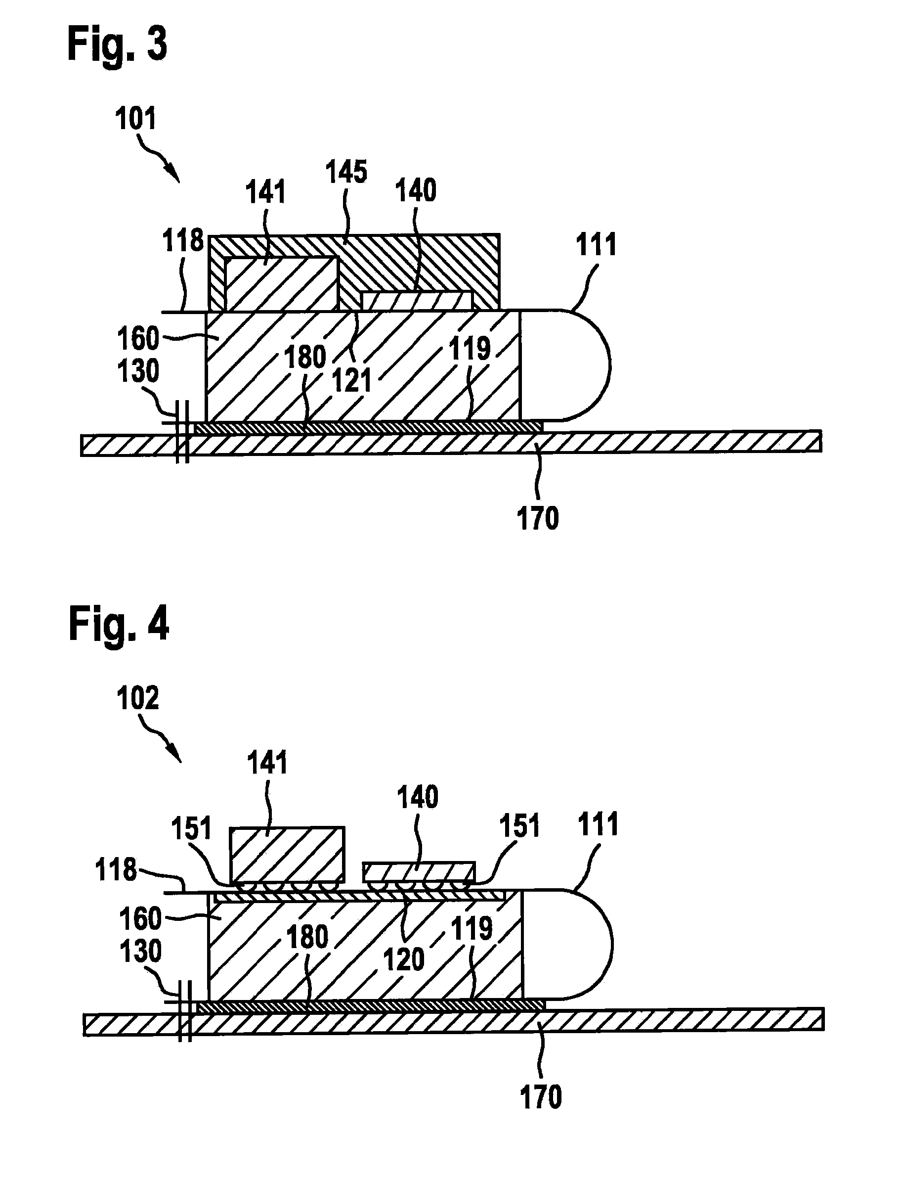
[0022]The following figures show possible specific embodiments of sensor devices, which are also designated as “sensor module” or “sensor package”. The sensor devices make possible the effective damping of a vibration-sensitive chip structure, and are distinguished by have a low space requirement. Safety systems of motor vehicles such as ESP (electronic stability program) come into consideration, for example, as fields of application of the sensor devices shown. In this instance, this may also involve those ESP systems in which the sensor devices are integrated in control units (or their housings) of ABS systems (anti-lock systems). The design of the sensor devices makes it possible reliably to damp vibrations and other mechanical interferences occurring in the operation of the ABS control units.

[0023]FIGS. 1 to 2 show the production of a sensor device 100, in each case in a lateral sectional representation. In the method, a flexible printed circuit board 111 is provided, on which a...


PUM

PropertyMeasurementUnit
Flexibilityaaaaaaaaaa
Areaaaaaaaaaaa

Abstract

A sensor device, having a flexible printed circuit board that has a fastening section for a chip structure, a chip structure situated on the fastening section of the flexible printed-circuit board, and a damper element for damping the chip structure from mechanical influences. The fastening section of the flexible printed circuit board, the chip structure and the damper element are situated one on top of the other.

Description

FIELD OF THE INVENTION[0001]The present invention relates a sensor device having a flexible printed circuit board, a chip structure situated on a fastening section of the flexible printed circuit board and a damping element for damping the chip structure from mechanical influences. The present invention also relates to a method for producing a sensor device.BACKGROUND INFORMATION[0002]Sensor devices which are used, for example, in security systems of motor vehicles, usually have a chip structure having a sensor chip and an evaluation chip that is electrically connected to the sensor chip. The sensor chip is developed in the form of a micromechanical component (MEMS, microelectromechanical system), in order to record a physical measured quantity, such as an acceleration or a rotational rate. The evaluation chip is used for controlling the sensor chip and for the evaluation or further processing of measuring signals of the sensor chip.[0003]Depending on their applications, the sensor ...

Claims


Application Information

Patent Timeline
IPC IPC(8): H05K1/18H05K3/30
CPCH01L23/3121H01L23/5387H01L2224/48091H01L2224/48137Y10T29/4913H01L2924/1461H01L2924/00014H01L2924/00H05K1/18
Inventor JOBERT, TRISTANHANSEN, UWE
Owner ROBERT BOSCH GMBH
Why Eureka
Try Eureka