
Light guide plate and backlight assembly having the same

Active Publication Date: 2013-02-21
AU OPTRONICS CORP
View PDF5 Cites 42 Cited by
  • Summary
  • Abstract
  • Description
  • Claims
  • Application Information

AI Technical Summary

Benefits of technology

The present invention provides a light guide plate that improves the efficiency of lighting and reduces hot spots, making the display panel brighter and better quality. Additionally, a horizontal connecting portion is included to further enhance the lighting efficiency. This improves the manufacturing quality and efficiency of the light guide plate.

Problems solved by technology

However, after entering the light incident surface of the wedge-shaped light guide plate, the light tends to leak out from the inclined surface before traveling to the light emitting region.
As a result, the light efficiency of the backlight assembly is deteriorated.
Moreover, display defects such as hot spots are likely to occur as well, thus lowering the display quality of the LCD device.

Method used


Image

  • Light guide plate and backlight assembly having the same
  • Light guide plate and backlight assembly having the same
  • Light guide plate and backlight assembly having the same

Examples


first embodiment

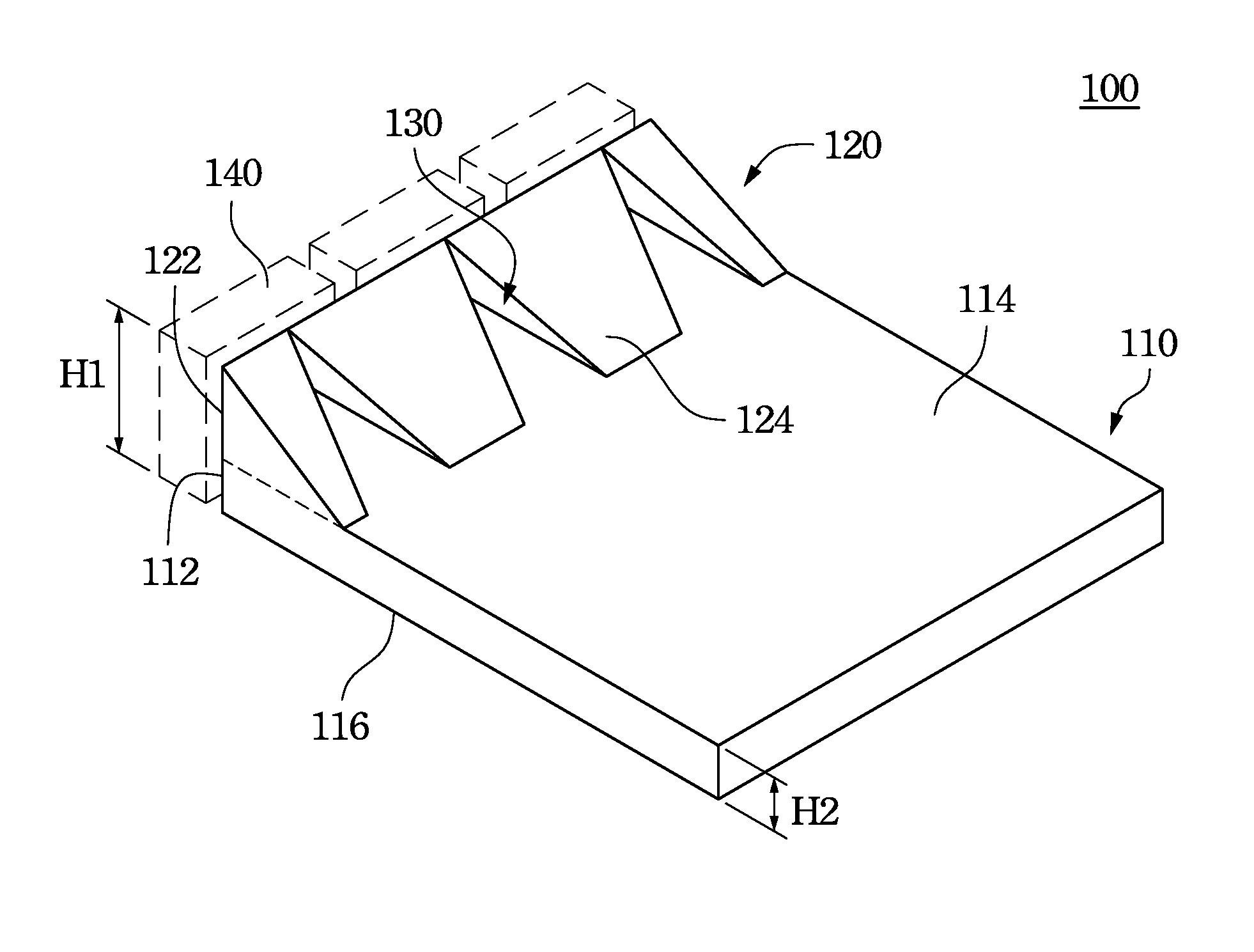
[0040]FIG. 1 is a perspective view illustrating a light guide plate according to the invention. A light guide plate 100 includes a main body portion 110 and inclined light guide portions 120. In addition, at least one recess 130 is formed between the inclined light guide portions 120. The main body portion 110 has a first light incident surface 112, a bottom surface 116, and a light emitting surface 114. The first light incident surface 112 faces toward a light source 140 and receives the light emitted by the light source 140. The light source 140 is exemplified by a point light source, such as a light emitting diode (LED) as shown in this embodiment. However, the light source 140 may also employ a linear light source, such a cold cathode fluorescent lamp (CCFL), or any other types of light sources. The bottom surface 116 is connected to the first light incident surface 112 in, for example, an orthogonal manner, and is used to reflect the light entering the first light incident surf...

third embodiment

[0064]In addition, the main body portion 810 has a first light incident surface 812, a bottom surface 816, and a light emitting surface 814. The functions and relationships of these surfaces are the same as those described in the third embodiment and are briefly described as follows.

[0065]As shown in the FIGS. 8, 9a and 9b, the inclined light guide portions 820 has a plurality of inclined surfaces, such as two inclined surface 824, and one end of each inclined surface 824 is connected together and another end thereof is connected to the wedge-shaped light guide portion 860 under the inclined light guide portions 820. The inclined surfaces 824 and the wedge-shaped light guide portion 860 under the inclined light guide portions 820 can cooperatively be connected to the light emitting surface 814 of the main body portion 810. Furthermore, such a structure may be implemented by forming the inclined light guide portions 820, the wedge-shaped light guide portion 860 and the main body port...


PUM


Abstract

A light guide plate includes a main body portion and inclined light guide portions having at least one recess. The main body portion has a first light incident surface, a bottom surface that is adjacent to the first light incident surface, and a light emitting surface that is opposite to the bottom surface. The inclined light guide portions disposed on the main body portion have a second light incident surface and at least one inclined surface. The second light incident surface is connected to the first light incident surface of the main body portion. The inclined surface is connected to the light emitting surface of the main body portion. At least one recess is formed between the inclined light guide portions. In addition, a wedge-shaped body can further be formed between the main body portion and the inclined light guide portions.

Description

RELATED APPLICATIONS[0001]This application claims priority to Taiwan Application Serial Number 100129434, filed Aug. 17, 2011 and 100142381, filed Nov. 18, 2011, which are herein incorporated by reference.BACKGROUND[0002]1. Field of Invention[0003]The present invention relates to a light guide plate and a backlight assembly having the same. More particularly, the present invention relates to a light guide plate having a recess and inclined light guide portions, and a backlight assembly having the same.[0004]2. Description of Related Art[0005]In general, a Liquid Crystal Display (LCD) device includes an LCD panel and a backlight assembly. The LCD panel includes a Thin Film Transistor (TFT) substrate, a Color Filter (CF) substrate, and a liquid crystal layer disposed between the two substrates. The backlight assembly provides light to the LCD panel so that images can be displayed.[0006]The light guide plate is an important component in the backlight assembly, and its main function is ...

Claims


Application Information

Patent Timeline
IPC IPC(8): G09F13/18G02B6/10
CPCG02B6/0028G02B6/0016G02B6/0018G02B6/0011
Inventor CHANG, YI-WENFAN, FU-CHENG
Owner AU OPTRONICS CORP
Features
  • Generate Ideas
  • Intellectual Property
  • Life Sciences
  • Materials
  • Tech Scout
  • Unparalleled Data Quality
  • Higher Quality Content
  • 60% Fewer Hallucinations
Learn More