Method for replacing a tunnel boring machine roller cutter, handling device and roller cutter suited to such a method

a technology of tunnel boring machine and roller cutter, which is applied in the direction of cutting machines, artificial islands, large fixed members, etc., can solve the problems of difficult access to the cutting head and the mounting hardware of the roller cutter, poor work compatibility, and exertion of considerable force, so as to avoid any component loss

Active Publication Date: 2013-02-21
BOUYGUES TRAVAUX PUBLICS SA
View PDF2 Cites 38 Cited by
  • Summary
  • Abstract
  • Description
  • Claims
  • Application Information

AI Technical Summary

Benefits of technology

[0016]Another object of the invention is to obtain a roller cutter handling device suited to the implementation of this method, by making it possible in particular to avoid any loss of components.

Problems solved by technology

The problem of changing the roller cutters occurs particularly in the case of a confined face tunnel boring machine, because access to the cutting head and to the roller cutter mounting hardware is difficult and the working environment is under hyperbaric conditions.
The procedure for changing a roller cutter often demands the exertion of considerable force (sledgehammer blows for example) for loosening the used roller cutter from its housing, due to jams and the absence of guidance for the roller cutter, which is poorly compatible with work under hyperbaric conditions.
Before inserting the new roller cutter into its housing, it must be properly positioned, which requires a painstaking manual intervention.
It will be understood that this procedure is long and tedious for the operators.

Method used


Image

  • Method for replacing a tunnel boring machine roller cutter, handling device and roller cutter suited to such a method
  • Method for replacing a tunnel boring machine roller cutter, handling device and roller cutter suited to such a method
  • Method for replacing a tunnel boring machine roller cutter, handling device and roller cutter suited to such a method

Examples


Embodiment Construction

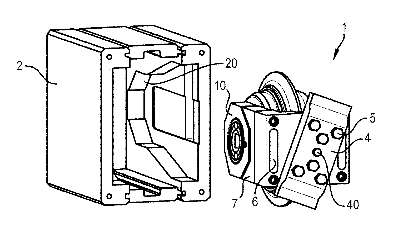
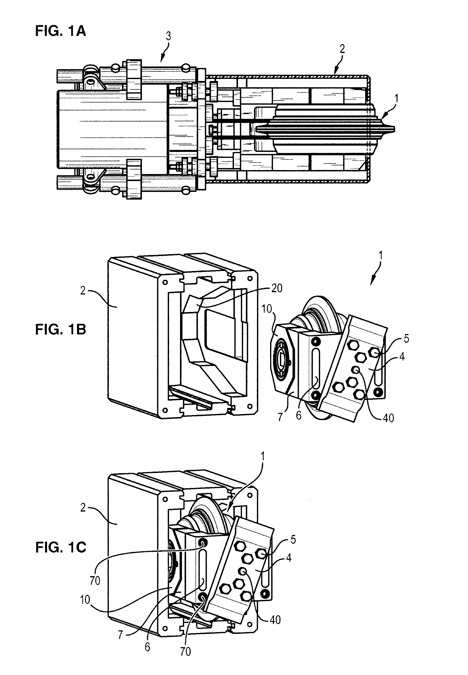
[0066]When the tunnel boring machine is put into service, each roller cutter is installed in its housing while being subjected to a preloading which allows it to resist the forces to which it will be subjected during cutting.

[0067]Conventionally, the housing for its part is affixed to the cutting head, typically by welding.

[0068]As will be seen below, the procedure for installation and extraction of the roller cutter is facilitated by the fact that the locking and preloading elements are permanently born by the roller cutter.

[0069]What is meant by “permanently born” is that the different elements allowing locking and preloading of the roller cutter within the housing can have relative motion with respect to one another, but that they remain mechanically connected to one another without the possibility of naturally separating.

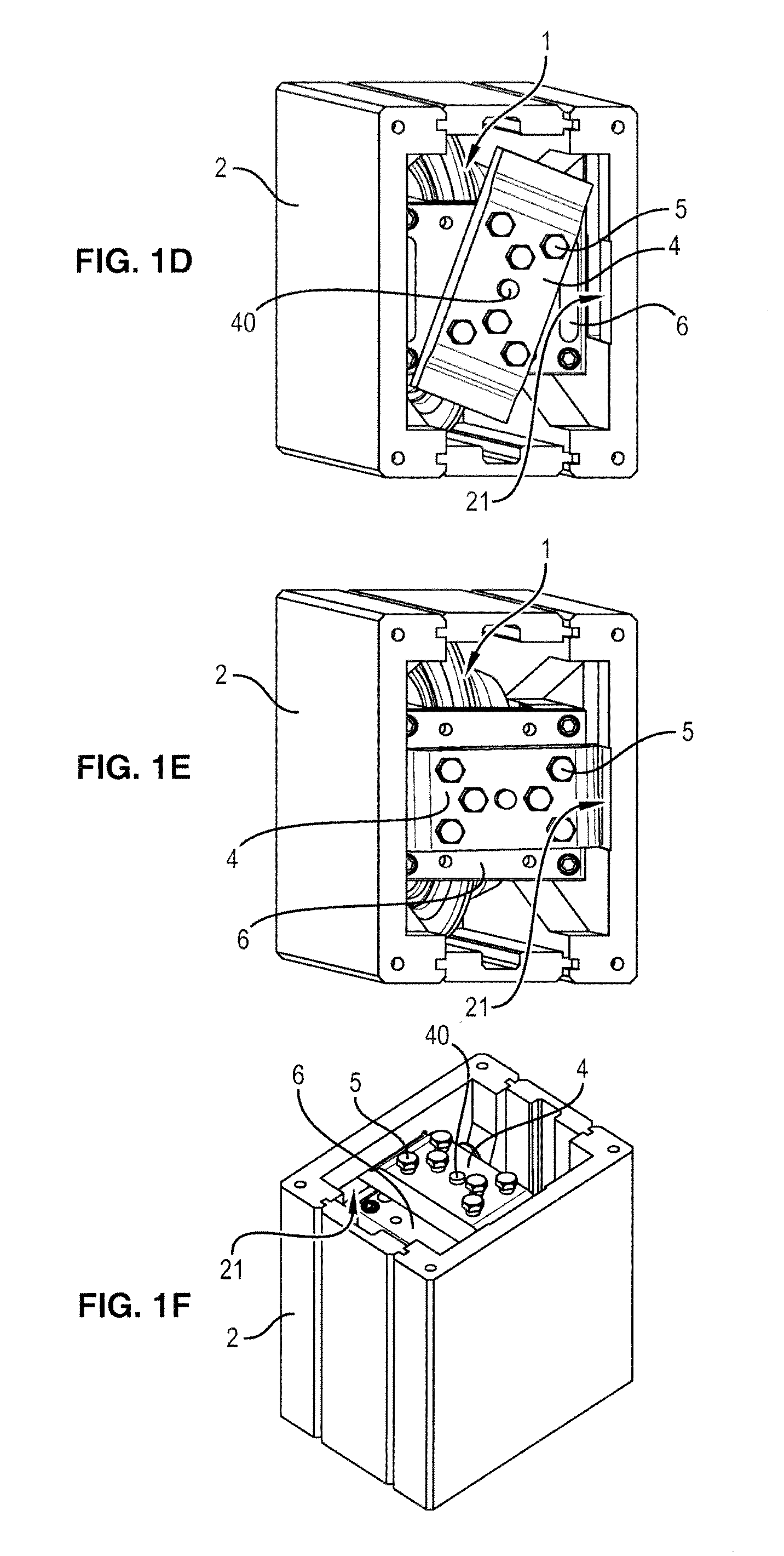
[0070]Method for Replacing a Roller Cutter

[0071]The extraction of a used roller cutter from its housing is implemented during the following steps.

[0072]Removal ...


PUM

PropertyMeasurementUnit
forceaaaaaaaaaa
atmospheric pressureaaaaaaaaaa
forcesaaaaaaaaaa

Abstract

The invention relates to a method for replacing a disk cutter (1) mounted with preload in a casing (2) attached to the cutting head of a tunnel boring machine, operated using a disk cutter (1) bearing, firmly attached thereto, an element (4) for locking into the housing (2) and preloading means (5), the method involving the steps of: a) removing a worn disk cutter (1) from said housing (2): • clamping a disk cutter (1) handling device (3) onto the housing (2); • taking hold of the disk cutter, • releasing the preload, • unlocking, • extracting the disk cutter (1), • unclamping the device (3), b) fitting a replacement disk cutter (1) in reverse order.

Description

FIELD OF THE INVENTION[0001]The present invention relates to a method for replacing a tunnel boring machine roller cutter on the cutting head of a tunnel boring machine, as well as a device for handling the roller cutter and a roller cutter suited to such a method.BACKGROUND OF THE INVENTION[0002]A roller cutter is a cutting tool that revolves freely around a shaft attached to the cutting head of a tunnel boring machine.[0003]During rotation of the head and under the influence of thrust, the roller cutter rolls over the cutting face and chips out the rock in the form of scale-like plates.[0004]Thus the cutting head includes a plurality of roller cutters evenly distributed over its surface.[0005]Conventionally, the roller cutters are mounted within a housing on the cutting head by means of bolts.[0006]The problem of changing the roller cutters occurs particularly in the case of a confined face tunnel boring machine, because access to the cutting head and to the roller cutter mounting...

Claims


Application Information

Patent Timeline
Patent Type & Authority Applications(United States)
IPC IPC(8): E21B10/627B23P19/00B23P11/00E21B10/12E21D9/10
CPCE21D9/104Y10T29/53991Y10T29/49817E21D9/0879E21B10/12E21D9/1013E21D9/08E21D9/10E21B10/20
Inventor DERYCKE, JEAN-NOELRUBRECHT, SEBASTIEN
Owner BOUYGUES TRAVAUX PUBLICS SA
Why Eureka
Try Eureka