
Low-noise bladeless fan

a bladeless fan, low-noise technology, applied in the direction of machines/engines, mechanical equipment, liquid fuel engines, etc., can solve the problems of noise at the interface between the air, easy to damage the blades, and difficult to clean, so as to reduce the noise of the fan

Inactive Publication Date: 2013-02-21
JIANGXI VITA TECH
View PDF4 Cites 43 Cited by
  • Summary
  • Abstract
  • Description
  • Claims
  • Application Information

AI Technical Summary

Benefits of technology

The present invention is a safe low-noise blades fan. It reduces the risk of injury from rotating blades and minimizes the noise generated by the fan. The fan includes several noise- reduction components, including a first component that isolates and separates out the noise created during operation, a second component that absorbs the noise generated in the outer casing, and a third component that improves the airflow and reduces noise through the use of through-holes in the bottom of the outer casing. These components work together to make the fan safer and quieter than previous designs.

Problems solved by technology

But such kind of traditional fans are prone to danger (e.g. some kids may put their fingers into a fan when they are not carefully watched and thereby would be hurt by the blades), including some hidden dangers, and are not easy to clean.
And noise will be caused at the interface between the air outlets and the internal passage for airflow under the action of air shear forces and other acting forces.
Meanwhile the impeller will also create noise during its operation.
Dust, oil stain and the like from the external environment are likely to come inside the fan through the air inlets during the operation of the fan, which also cause more noise.
Further, bladeless fan devices are also disclosed in other patent reference documents, such as CN201568337U, KR100985378, HK1146191; but no solutions are raised to efficiently reduce the noise created in the bladeless fan.

Method used


Image

  • Low-noise bladeless fan
  • Low-noise bladeless fan
  • Low-noise bladeless fan

Examples


Embodiment Construction

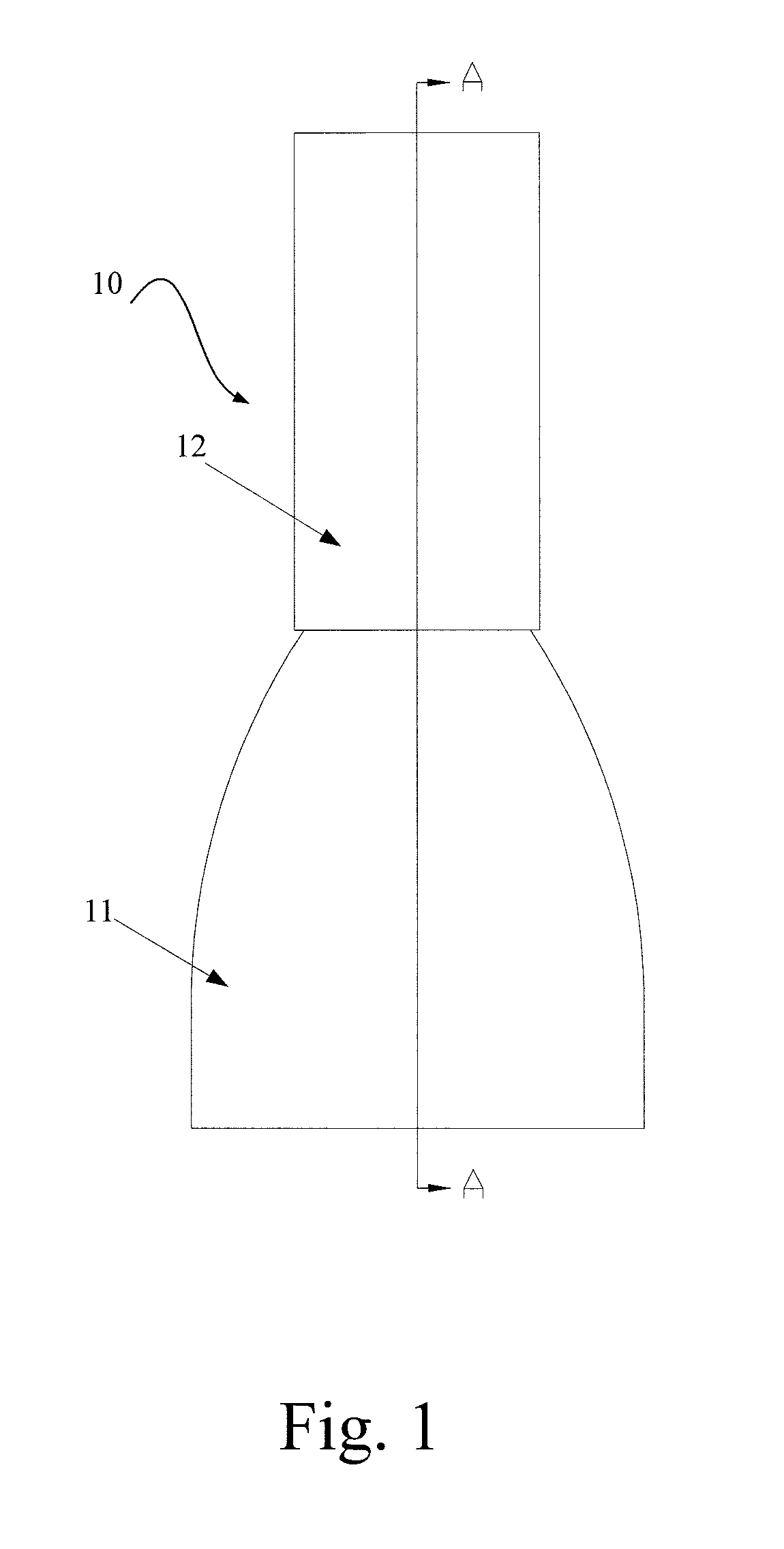
[0023]FIG. 1 shows a side view of a low-noise bladeless fan 10 including a base 11 and a nozzle 12.

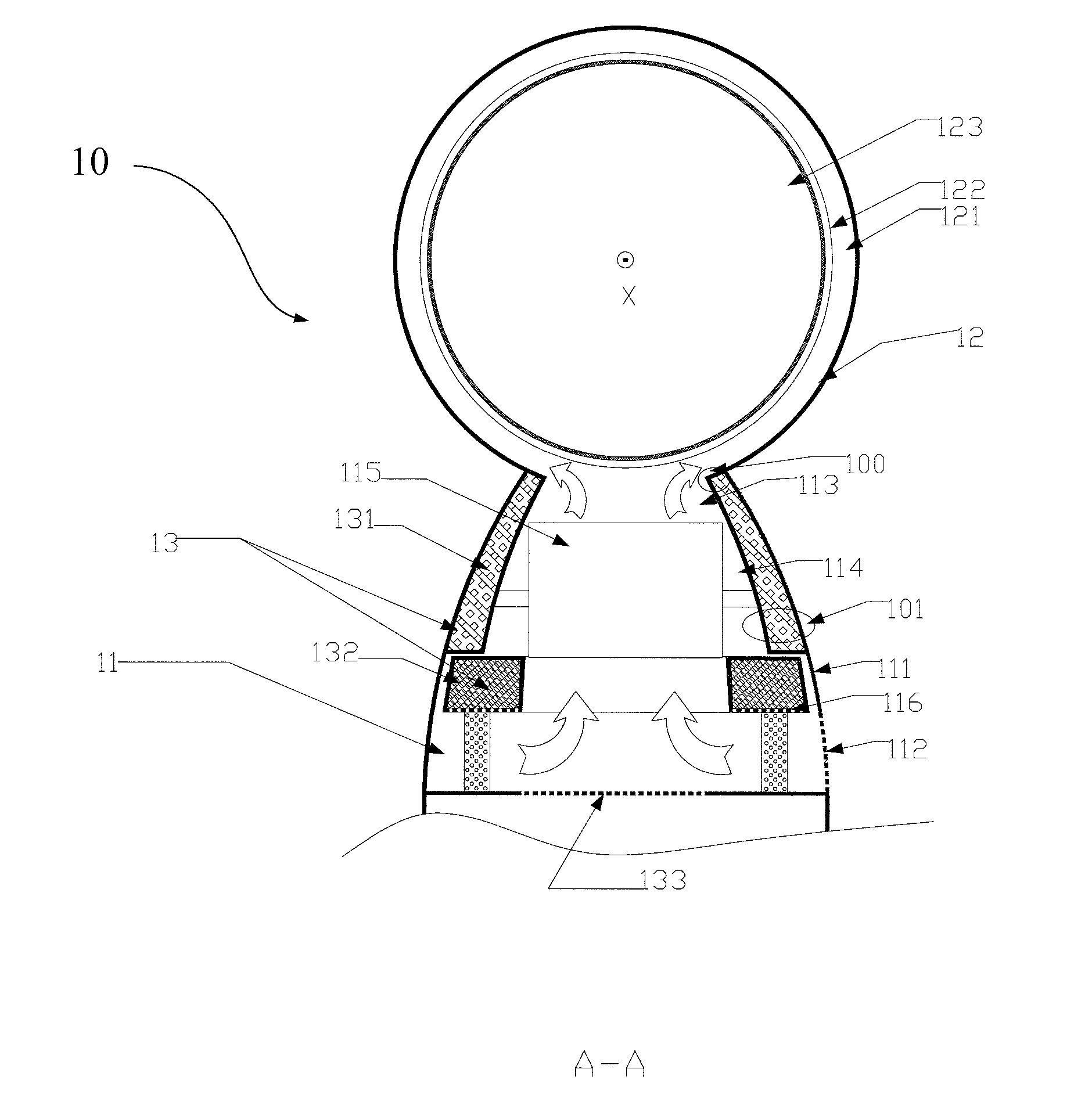
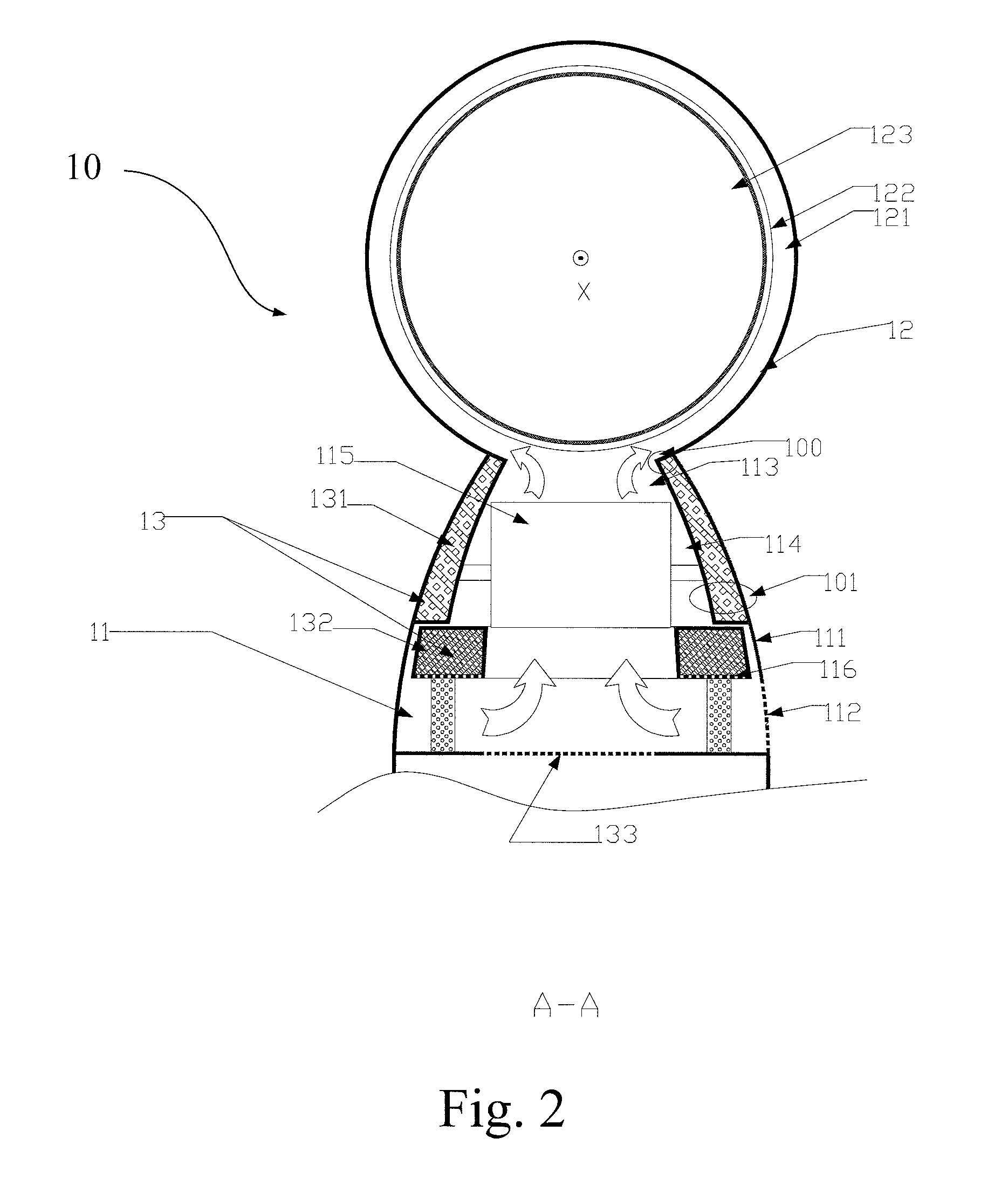
[0024]As shown in FIG. 2, the low-noise bladeless fan 10 comprises the nozzle 12 located at the top of the base 11, and noise-reduction components 13 located within the base 11.

[0025]As a major mounting assembly of the low-noise bladeless fan, the base 11 can have an arced shape, a cylindrical shape, a cuboid shape or other shapes.

[0026]The base 11 comprises an outer casing 111, air inlets 112, air outlets 113, air ducts 114 between the air inlets 112 and the air outlets 113, as well as an impeller 115 and an impeller fixture 116 accommodated in the outer casing 111.

[0027]The outer casing 111 is a casing body with an opening at one end thereof, the opening being in communication with the nozzle 12. The outer casing 111 has a shape designed based on actual design demand and not confined to the present embodiment.

[0028]The air inlets 112 are a plurality of through-holes disposed on a sid...


PUM


Abstract

A low-noise bladeless fan includes a base, a nozzle at the top of the base and noise-reduction components located within the base. The noise-reduction components include a first noise-reduction component, a second noise-reduction component and a third noise-reduction component. The first noise-reduction component is located at an interface between air outlets and an internal passage for airflow reduces noise by isolating, obstructing and separating noise created inside the outer casing. The second noise-reduction component is disposed within an impeller fixture reduces noise by absorbing noise created inside the outer casing. Through-holes are disposed in the bottom of the outer casing act as the third noise-reduction component and also reduce noise. The arrangement of noise-reduction components can reduce noise created in the fan, thereby cooling users with natural and soft wind.

Description

CROSS REFERENCE TO RELATED APPLICATION[0001]This application claims the benefit of and priority to Chinese Patent Application No. 201110234196.7, filed on Aug. 16, 2011, which is owned by the instant application and the disclosure of which is incorporated herein by reference in its entirety.FIELD OF THE INVENTION[0002]The present invention relates to bladeless fan, and particularly relates to a low-noise bladeless fan.BACKGROUND OF THE INVENTION[0003]Traditional fans are operated in such a way: an electric motor drives blades to rotate so as to create wind and to speed up air flow in the surrounding environment, for cooling and heat-relieving and ventilation. But such kind of traditional fans are prone to danger (e.g. some kids may put their fingers into a fan when they are not carefully watched and thereby would be hurt by the blades), including some hidden dangers, and are not easy to clean.[0004]A type of bladeless fan device for creating airflow is disclosed in an patent applica...

Claims


Application Information

Patent Timeline
IPC IPC(8): F04D29/66
CPCF04F5/16F04D25/08
Inventor TU, JINHUAXIONG, XIONGZHANG, XIAOMINGXIONG, CHUANWEI
Owner JIANGXI VITA TECH
Learn More