
Carbon dioxide bed bug detection system

a detection system and carbon dioxide technology, applied in the field of carbon dioxide bed bug detection system, can solve the problems of not all solutions are fully effective, adverse economic consequences, skin rashes, etc., and achieve the effect of greater holding power (adhesivity) of the glue layer

Inactive Publication Date: 2013-02-28
FRISCH JONATHAN
View PDF8 Cites 16 Cited by
  • Summary
  • Abstract
  • Description
  • Claims
  • Application Information

AI Technical Summary

Benefits of technology

The patent describes a bed bug detection system that includes a container, tubes, and detector stations. The system works by releasing solidified carbon dioxide from the container and allowing it to flow through the tubes to the detector stations. The detector stations have a housing with an open first and second end, and a trapping chemical inside. The system can be used to detect bed bugs by positioning the detector stations in areas where bed bugs may be present and observing any captured bed bugs. The technical effects of the system include improved accuracy and efficiency in detecting bed bugs, as well as a simplified and user-friendly installation process.

Problems solved by technology

The emotion of fear is both healthwise and the difficult nature of exterminating the problem.
Amongst adverse health effects resulting from bites are possible skin rashes, psychological effects, and allergic symptoms.
The problem is manifest in a hotel or other public residency; there can be adverse economic implications resultant from the negative publicity.
Not all solutions are fully effective.
Although the trap described therein is effective, expensive chemical lures are necessary and speed of detection is relatively slow.

Method used


Image

  • Carbon dioxide bed bug detection system
  • Carbon dioxide bed bug detection system
  • Carbon dioxide bed bug detection system

Examples


Embodiment Construction

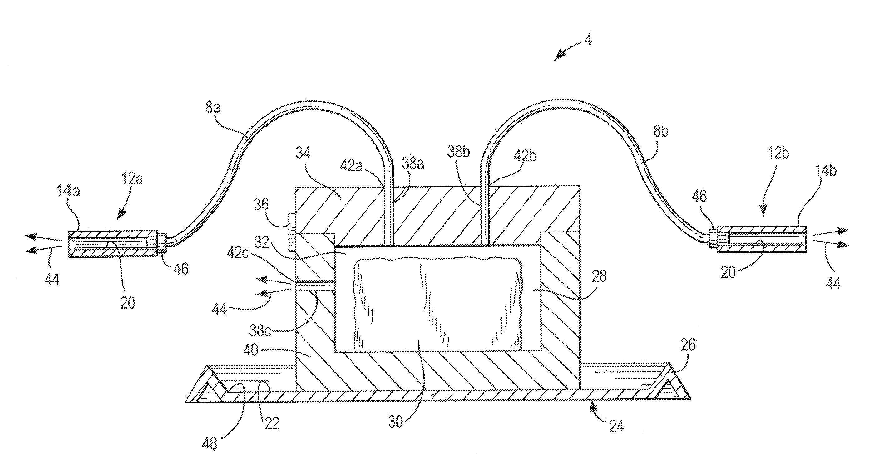
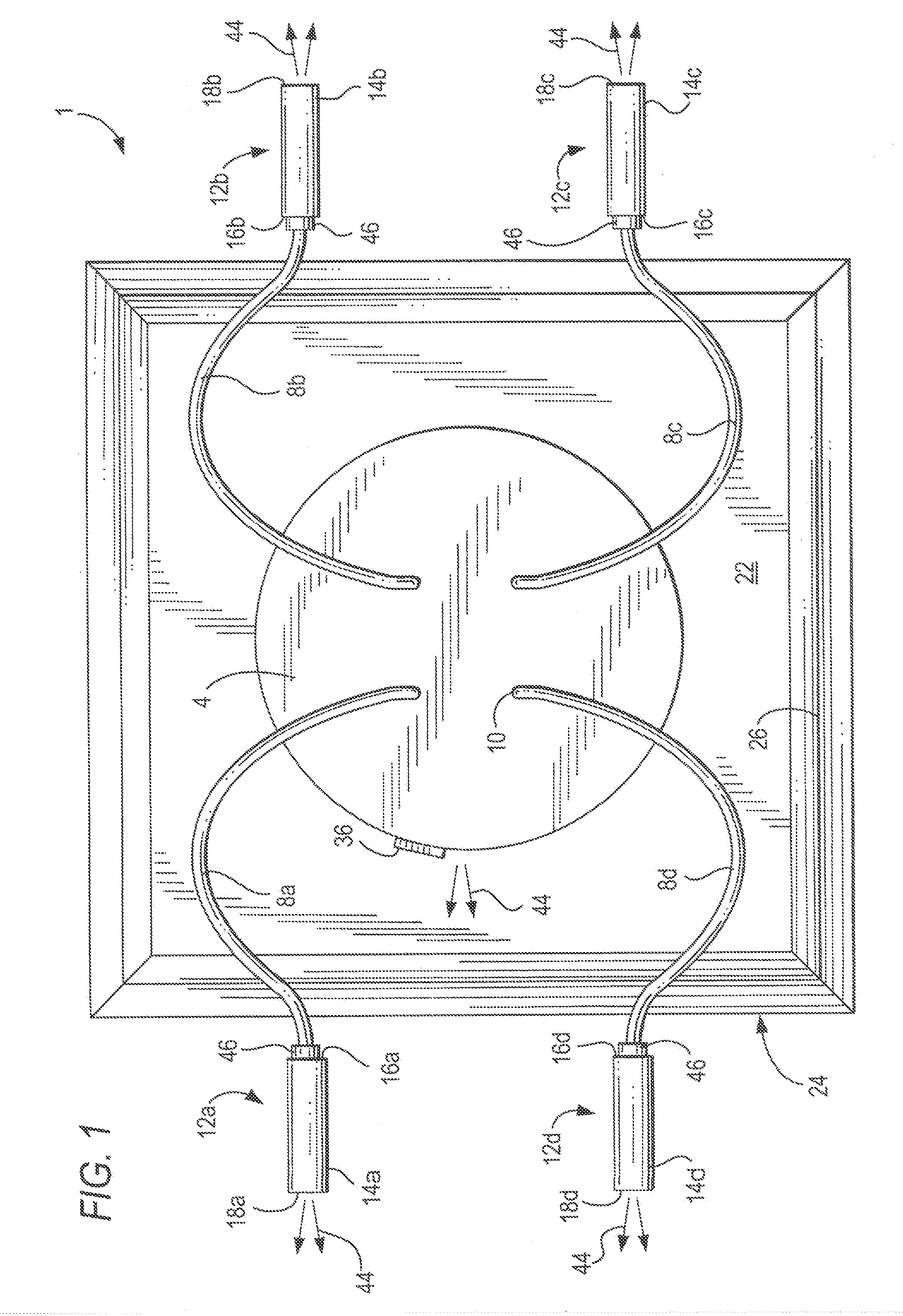
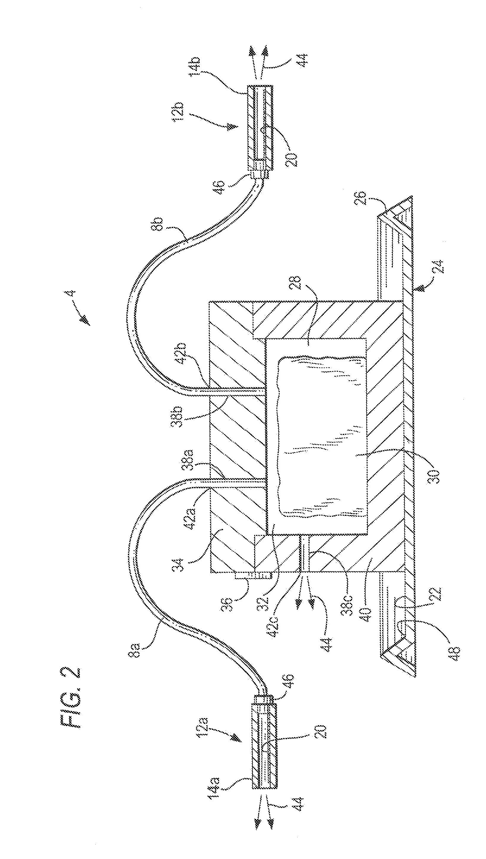
[0031]With reference to the drawings, FIGS. 1-3 show a carbon dioxide bed bug detection system, according to the present invention, which includes a lockable insulated carbon dioxide container, a plurality of bed bug detector stations and a plurality of tubes which connect the bed bug detector stations and the carbon dioxide filled container.

[0032]During use, a solid block of carbon dioxide, or dry ice, is placed inside a receiving chamber of the container and the top cover is locked in place. The locked cover prevents accidental, unwanted contact with the solid carbon dioxide. The insulated walls of the container prolong the sublimation time of the dry ice and prolong the time during which carbon dioxide vapor flows through the tubes and into the bed bug detector stations.

[0033]The ends of the tubes each have a fitting, shown typically in FIG. 3 which introduces the carbon dioxide vapor into the space formed by panels of the housing defining bed bug detector stations. The carbon di...


PUM


Abstract

A bed bug detection system is provided which includes a container having a receiving chamber for holding solidified carbon dioxide, an opening in the chamber communicating with and of sufficient size to insert the solidified carbon dioxide into the receiving chamber, a removable cover fitting over the opening, a plurality of channels formed in walls of the container, the channels allowing flow from the chamber of carbon dioxide to exit outside the walls of the container, exit occurring at exit ports; a plurality of tubes formed of a polymeric material, each tube connected to an exit port; and a plurality of bed bug detector stations, each station attached to one of the plurality of tubes, each of the stations formed of a housing with open first and second ends, and a trapping chemical being deposited within each housing.

Description

REFERENCE TO RELATED CASES[0001]This application claims priority from Provisional Application Ser. No. 61 / 445,131, filed Feb. 22, 2011.FIELD OF THE INVENTION[0002]The present invention is directed towards a carbon dioxide bed bug detection system.BACKGROUND OF THE INVENTION[0003]Fear and shame are two human emotions associated with a bed bug infestation. The emotion of fear is both healthwise and the difficult nature of exterminating the problem. Amongst adverse health effects resulting from bites are possible skin rashes, psychological effects, and allergic symptoms.[0004]The emotion of shame is related to a perceived lack of cleanliness. The problem is manifest in a hotel or other public residency; there can be adverse economic implications resultant from the negative publicity.[0005]Bed bugs are parasitic insects that prefer to feed on human blood. The name of the “bed bug” is derived from the insect's preferred habitat of houses. Most especially they prefer beds or other areas w...

Claims


Application Information

Patent Timeline
Patent Type & Authority Applications(United States)
IPC IPC(8): A01M1/10A01M1/00A01M1/14
CPCA01M1/10A01M1/026A01M1/023A01M1/14Y02A50/30
Inventor FRISCH, JONATHAN
Owner FRISCH JONATHAN
Learn More