Minimum strain energy waypoint-following controller for directional drilling using optimized geometric hermite curves

a technology of geometric hermite curves and controllers, applied in the direction of directional drilling, rotary drilling, percussion drilling, etc., can solve the problems of inability to minimize the strain energy of drilling components, inconvenient maintenance and attention of personnel, and inaccuracy of controlling capabilities

Active Publication Date: 2013-02-28
SCHLUMBERGER TECH CORP
View PDF2 Cites 25 Cited by
  • Summary
  • Abstract
  • Description
  • Claims
  • Application Information

AI Technical Summary

Problems solved by technology

Current drilling controllers, for example, have significant drawbacks that include inaccurate controlling capability and inability to minimize strain energy on drilling components.
In addition to these drawbacks, conventional systems require constant maintenance and attention by personnel.

Method used


Image

  • Minimum strain energy waypoint-following controller for directional drilling using optimized geometric hermite curves
  • Minimum strain energy waypoint-following controller for directional drilling using optimized geometric hermite curves
  • Minimum strain energy waypoint-following controller for directional drilling using optimized geometric hermite curves

Examples


Embodiment Construction

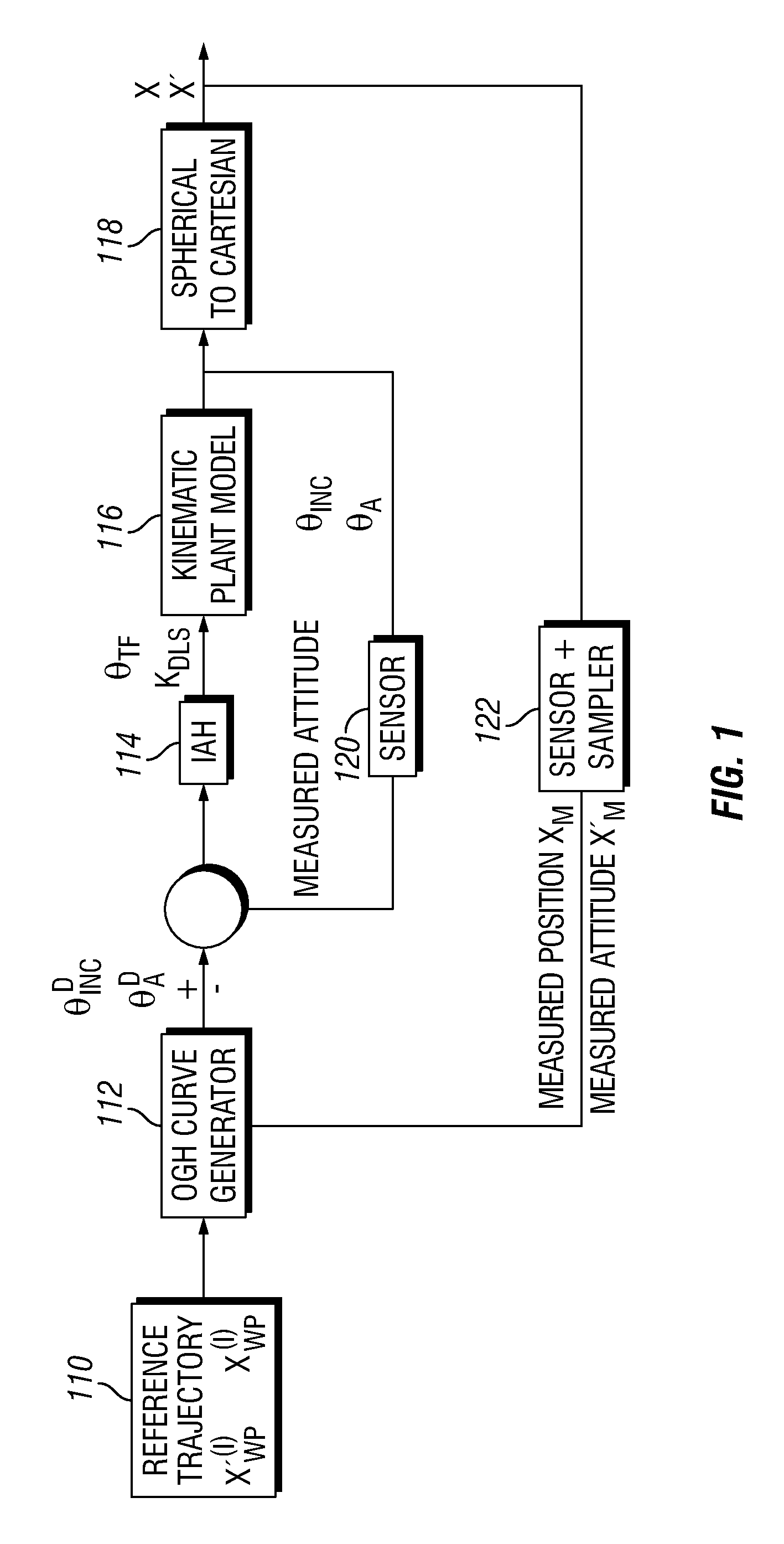
[0015]Aspects described present, in one non-limiting embodiment, the application of Optimized Geometric Hermite (“OGH”) curves as a method for real-time path planning and following for directional drilling tools which have the ability to hold inclination and azimuth. In the embodiments presented, different drilling apparatus may be controlled, such as a drill string or coiled tubing drilling, as non-limiting embodiments. In embodiments presented, the method and apparatus rely on a target position in space ahead of the drill bit with an associated target attitude. These targets, or waypoints, may be used as a sequence of points with attitudes corresponding to a well plan which is to be followed, or, in an alternative embodiment, they may be a finite number of points in space which may correspond to strategic points in a pay zone (a reservoir or portion of a reservoir that contains economically producible hydrocarbons is known as a pay or pay zone). In additional applications, this me...


PUM


Abstract

A method and apparatus for controlling drilling, the method comprising ascertaining a current position and attitude of a drilling structure, obtaining a desired end point for the drilling structure, creating an optimized geometric Hermite curve path for the drilling structure from the current position and attitude of the drilling structure to the desired end point for the drilling structure and controlling a drilling of the drilling structure from the current position and attitude of the drilling structure to the desired end point for the drilling structure along the optimized geometric Hermite curve path.

Description

FIELD OF THE INVENTION[0001]The present disclosure relates to directional drilling. More specifically, aspects of the disclosure relate to providing a minimum strain energy waypoint following controller arrangement and method for directional drilling applications.BACKGROUND INFORMATION[0002]As the future of directional drilling moves toward the exploitation of increasingly complex reservoirs, there is a desire and a need for automating rig operations as much as possible. The implications and advantages of such automated rig operations would enable rig operation teams to focus on higher levels of decision making, hence increasing safety and economic return.[0003]Current drilling controllers, for example, have significant drawbacks that include inaccurate controlling capability and inability to minimize strain energy on drilling components. In addition to these drawbacks, conventional systems require constant maintenance and attention by personnel. There is a need to provide a drillin...

Claims


Application Information

Patent Timeline
Patent Type & Authority Applications(United States)
IPC IPC(8): E21B7/04E21B7/20
CPCE21B7/04E21B44/00
Inventor PANCHAL, NEILKUNALBAYLISS, MARTINWHIDBORNE, JAMES
Owner SCHLUMBERGER TECH CORP
Why Eureka
Try Eureka