
Screened Inline Flow-through (SIFT) Sediment Trap Apparatus

a sediment trap and flow-through technology, applied in the direction of filtration separation, separation processes, instruments, etc., can solve the problems of significant labor hours for sediment separation, bottle-type sediment traps require significant installation and maintenance, and the volume of stormwater solids captured is insufficien

Active Publication Date: 2013-02-28
CITY OF PORTLAND OREGON
View PDF0 Cites 3 Cited by
  • Summary
  • Abstract
  • Description
  • Claims
  • Application Information

AI Technical Summary

Benefits of technology

The patent describes a new device called the SIFT that can capture a measurable portion of solid particles from discrete storm events, resulting in an integrated sample of solids over the course of a wet season. This is important because it is currently unclear whether standard sediment traps capture all of the solids from all storm events or just a portion of the total solids fraction from a few large pests. The SIFT is flexible and can be installed in different small-pipe diameters, and it offers clear advantages over the standard sediment trap, including easier installation and removal and faster processing times. More importantly, the SIFT appears to capture a portion of the solids fraction during discrete storm events, resulting in a truly integrated sample of solids over time.

Problems solved by technology

This known type of inline sediment trap is commonly deployed; yet, these trap deployments have captured insufficient volumes of stormwater solids to meet all analytical objectives, such as in a City of Portland (Oreg., USA) study where installed sediment traps were placed in a variety of locations within the stormwater conveyance system during the 2007 and 2008 wet seasons.
From this collection effort various observations of limitations in the known art were made and such limitations included that the bottle-type sediment traps required significant labor hours to install, and significant labor hours to separate the sediment from the fluid in the lab at the end of a deployment period before solids analysis.
Other limitations include a large profile, and the resulting inability to be easily installed and removed or to capture adequate stormwater solids in small-pipe diameters (i.e., in pipe diameters less than 30 inches.

Method used


Image

  • Screened Inline Flow-through (SIFT) Sediment Trap Apparatus
  • Screened Inline Flow-through (SIFT) Sediment Trap Apparatus
  • Screened Inline Flow-through (SIFT) Sediment Trap Apparatus

Examples


Embodiment Construction

[0030]Possible preferred embodiments will now be described with reference to the drawings and those skilled in the art will understand that alternative configurations and combinations of components may be substituted without subtracting from the invention. Also, in some figures certain components are omitted to more clearly illustrate the invention.

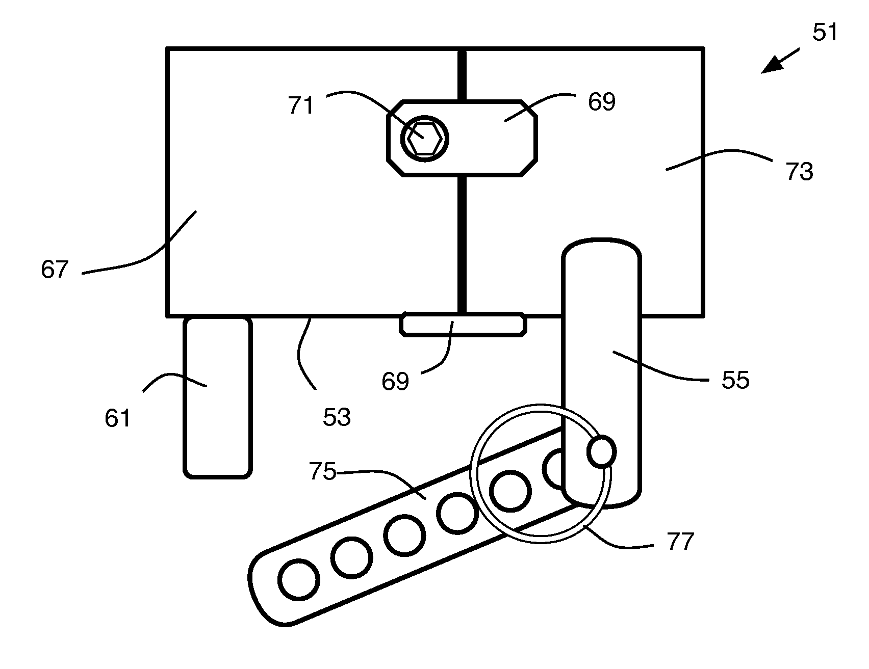
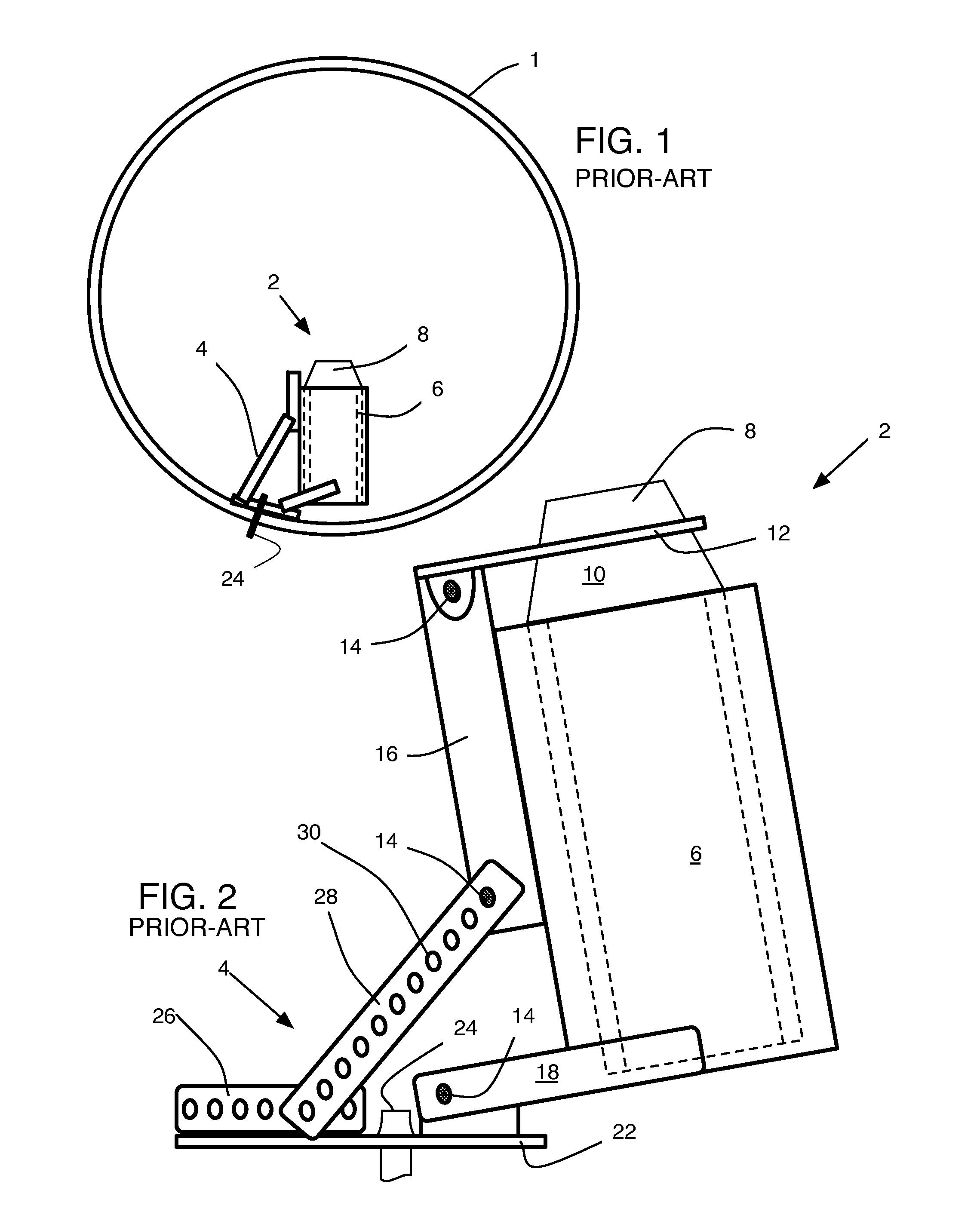
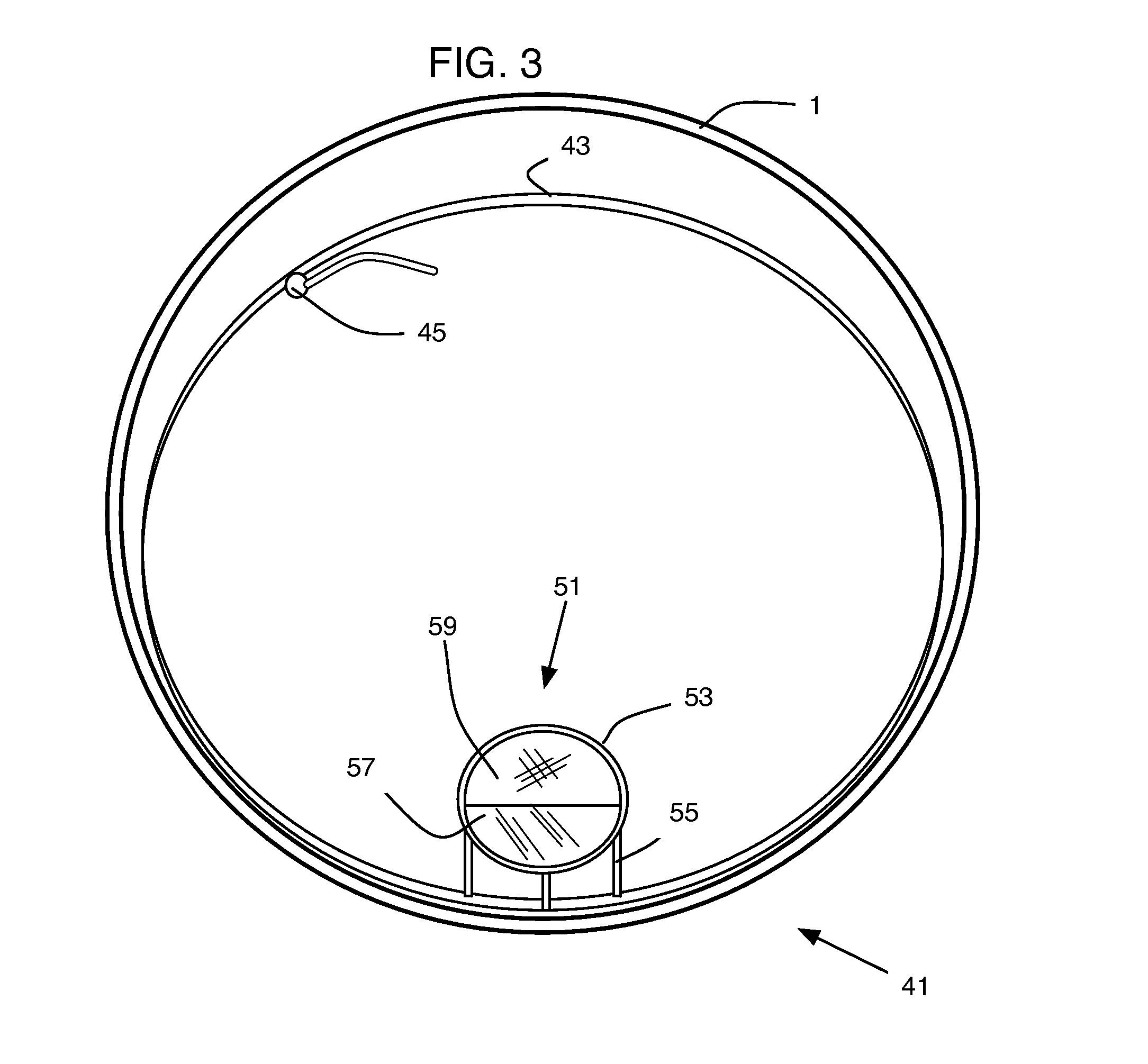
[0031]FIG. 1 illustrates a known sediment trap 2 for placement in a pipe 1. Such a trap 2 include a housing 6 supported by a bracket assembly 4. The bracket assembly is bolted to a sidewall of the pipe. The housing supports a plastic collection bottle 8 using a securing band 12. The opening of the bottle is placed perpendicular to the flow of the effluent stream in the pipe. And sediment is deposited in the narrow opening, along with fluid and fluid with suspended solids. Because the bottle opening must be perpendicular to the flow of the effluent stream, this conventional trap requires a considerable amount of headroom, effectively limit...


PUM

PropertyMeasurementUnit
Lengthaaaaaaaaaa
Lengthaaaaaaaaaa
Diameteraaaaaaaaaa

Abstract

An improved sediment trap is adapted for inline placement in a pipe. The sediment trap includes a housing body defining two chambers with an intermediate screen member disposed therebetween. The first chamber includes at least one sidewall coupled to a partial front wall wherein the partial front wall, which is disposed at an end opposite from the intermediate screen member. The second chamber includes at least one sidewall and a rear mesh screen. When placed in-line, the effluent stream deposits solids of a first size in the first chamber and deposits solids of a second size in the second chamber.

Description

BACKGROUND[0001]The present invention relates to collection devices that arrange inside pipelines and similar fluid conveyance systems to trap samples and, more specifically, devices placed in stormwater pipelines to collect suspended sediment samples.[0002]Inline sediment traps are one of many sampling tools utilized by municipalities, environmental agencies, and private parties to characterize piped pathways to receiving waters and to support ongoing contaminant investigations. A known sediment trap apparatus consists of a stainless steel bracket that bolts to the pipeline wall and the bracket supports a cylindrical housing fixture. The cylindrical housing fixture supports a 1-liter (L) high-density polyethylene (HDPE) sample bottle. The sample bottle is retained in the fixture by a securing band placed around the neck of the sample bottle, and the sample-bottle's open top arranges generally perpendicular to the flow of the effluent stream (see FIG. 1).[0003]This known type of inl...

Claims


Application Information

Patent Timeline
IPC IPC(8): B01D35/28B01D35/30
CPCE03F5/14F16L55/24G01N2001/1093G01N2001/1025G01N2001/1012
Inventor BAWDEN, JEREMIAHBELSTON, RANDY CHRISTOPHERSULLIVAN, MATTHEW JOSEPH
Owner CITY OF PORTLAND OREGON
Learn More