LED drive circuit and LED driving method

Active Publication Date: 2013-02-28
SHARP KK
View PDF3 Cites 9 Cited by
  • Summary
  • Abstract
  • Description
  • Claims
  • Application Information

AI Technical Summary

Benefits of technology

[0015]According to an LED drive circuit of the present invention, light control can be carried out, in a region where a light control level is equal to or greater than the certain light control level, by adjusting a pulse height of an LED drive current. This makes it unnecessary to increase an oscillation frequency of a DC-to-DC converter even in a case where a light control level is increased. Also, light control is carried out, in a region where a light control level is equal to or less than the certain light control level, by adjusting an off period of oscillation of the DC-to-DC converter. This causes an oscillation frequenc

Problems solved by technology

However, this method will cause a problem that flickering occ

Method used


Image

  • LED drive circuit and LED driving method
  • LED drive circuit and LED driving method
  • LED drive circuit and LED driving method

Examples


Embodiment Construction

Basic Configuration of LED Drive Circuit Using DC-to-DC Converter

[0027]An embodiment of the present invention is described below in detail with reference to the drawings. The following description will discuss an example in which the present invention is applied to an LED drive circuit of buck converter type. Note, however, that the present invention is applicable to LED drive circuits of buck converter type and of buck-boost converter type.

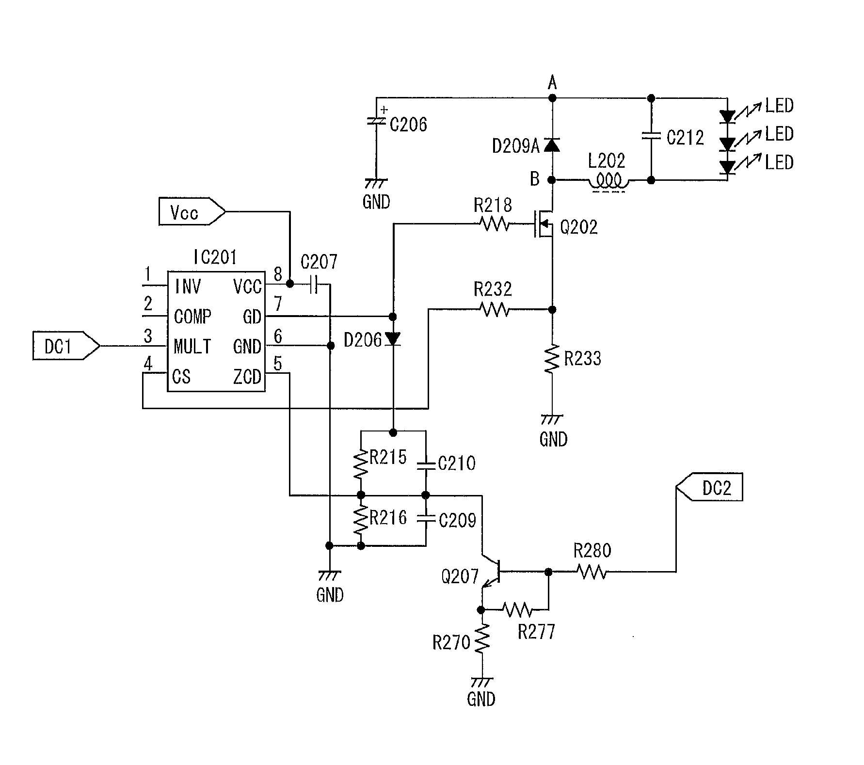
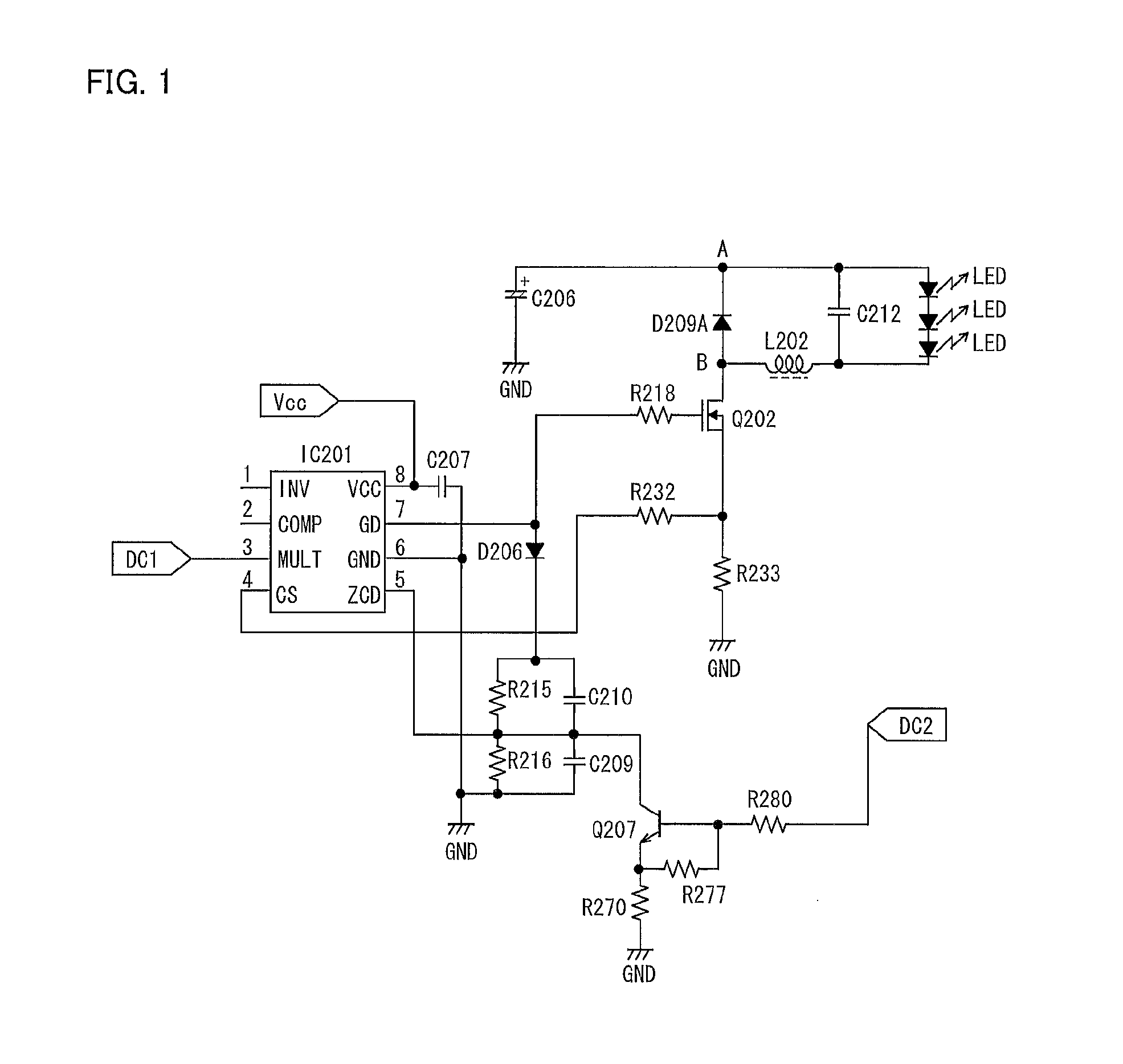
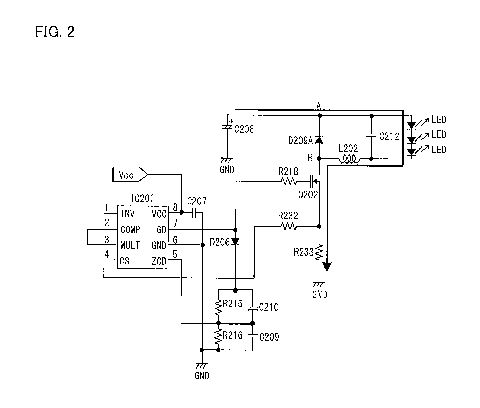
[0028]FIG. 2 and FIG. 3 are circuit diagrams each showing a typical circuit configuration of an LED drive circuit employing a conventional PWM light control method. Each of the LED drive circuits is a constant current circuit using, as a control IC, an L6562 manufactured by STMicroelectronics N.V. FIG. 4 illustrates how an electric current flows to an LED in a case where the LED is driven by the LED drive circuit shown in each of FIG. 2 and FIG. 3. The LED drive circuit includes a DC-to-DC converter of buck converter type (hereinafter, referred t...


PUM


Abstract

An LED drive circuit of the present invention carries out, by use of a DC-to-DC converter, light control of an LED. The light control is carried out, in a region where a light control level is equal to or greater than a certain light control level, by a DC light control method for adjusting a pulse height of an LED drive current. The light control is carried out, in a region where a light control level is equal to or less than the certain light control level, by a PDM light control method for adjusting an off period of oscillation of the DC-to-DC converter.

Description

[0001]This Nonprovisional application claims priority under 35 U.S.C. §119 on Patent Application No. 2011-185146 filed in Japan on Aug. 26, 2011, the entire contents of which are hereby incorporated by reference.TECHNICAL FIELD[0002]The present invention relates to an LED (Light Emitting Diode) drive circuit of buck converter type or buck-boost converter type.BACKGROUND ART[0003]An LED drive circuit has been known that (i) supplies a constant current to an LED by use of a DC-to-DC converter and (ii) carries out light control of the LED by changing a value of the constant current. As a method for supplying a constant current to an LED, a method is known in which an output current is detected by use of a resistor etc. and carries out voltage feedback so that the LED receives a desired current (see, for example, Patent Literature 1). However, this method will cause a problem that flickering occurs typically in a light control region of not more than 10%.[0004]In order to avoid the prob...

Claims


Application Information

Patent Timeline
IPC IPC(8): H05B37/02H05B44/00
CPCH05B33/0818H05B45/3725H05B45/375
Inventor MURAKAMI, KOHZABUROH
Owner SHARP KK
Why Eureka
Try Eureka