
filter

a filter and filter body technology, applied in the field of filters, can solve the problems of large size of filter equipment, unsuitable implementation, complicated body shape,

Inactive Publication Date: 2013-02-28
MESAPLEXX
View PDF6 Cites 2 Cited by
  • Summary
  • Abstract
  • Description
  • Claims
  • Application Information

AI Technical Summary

Benefits of technology

The present invention provides a cavity filter that includes a dielectric resonator structure and a coupling structure for exciting a resonant mode within the structure or extracting energy from the structure. The coupling structure consists of a single patch element in contact with a surface of the dielectric material. The filter can be designed to have a high degree of coupling between the resonant modes, allowing for simultaneous excitation or energy extraction. The filter can also be designed to have a flat conductive element that can generate an electric field for exciting both modes simultaneously. The shape of the dielectric material can be designed to cause excitation of the second resonant mode when the first resonant mode is excited. The filter can also have a layer of conductive material with a aperture in which the coupling structure is located. The invention provides a cavity filter with improved coupling between the resonant modes and improved performance.

Problems solved by technology

A number of resonators will usually be required to achieve suitable filtering characteristics for commercial applications, resulting in filtering equipment of a relatively large size.
However, the size of single mode filters as described above can make these undesirable for implementation at the top of antenna towers.
However, the approach used to couple energy into and out of the resonator, and between the modes within the resonator to provide the effective resonator cascade, requires the body to be of complicated shape, increasing manufacturing costs.
In any case the physical complexity and hence manufacturing costs are even further increased.

Method used


Image

  • filter
  • filter
  • filter

Examples


Embodiment Construction

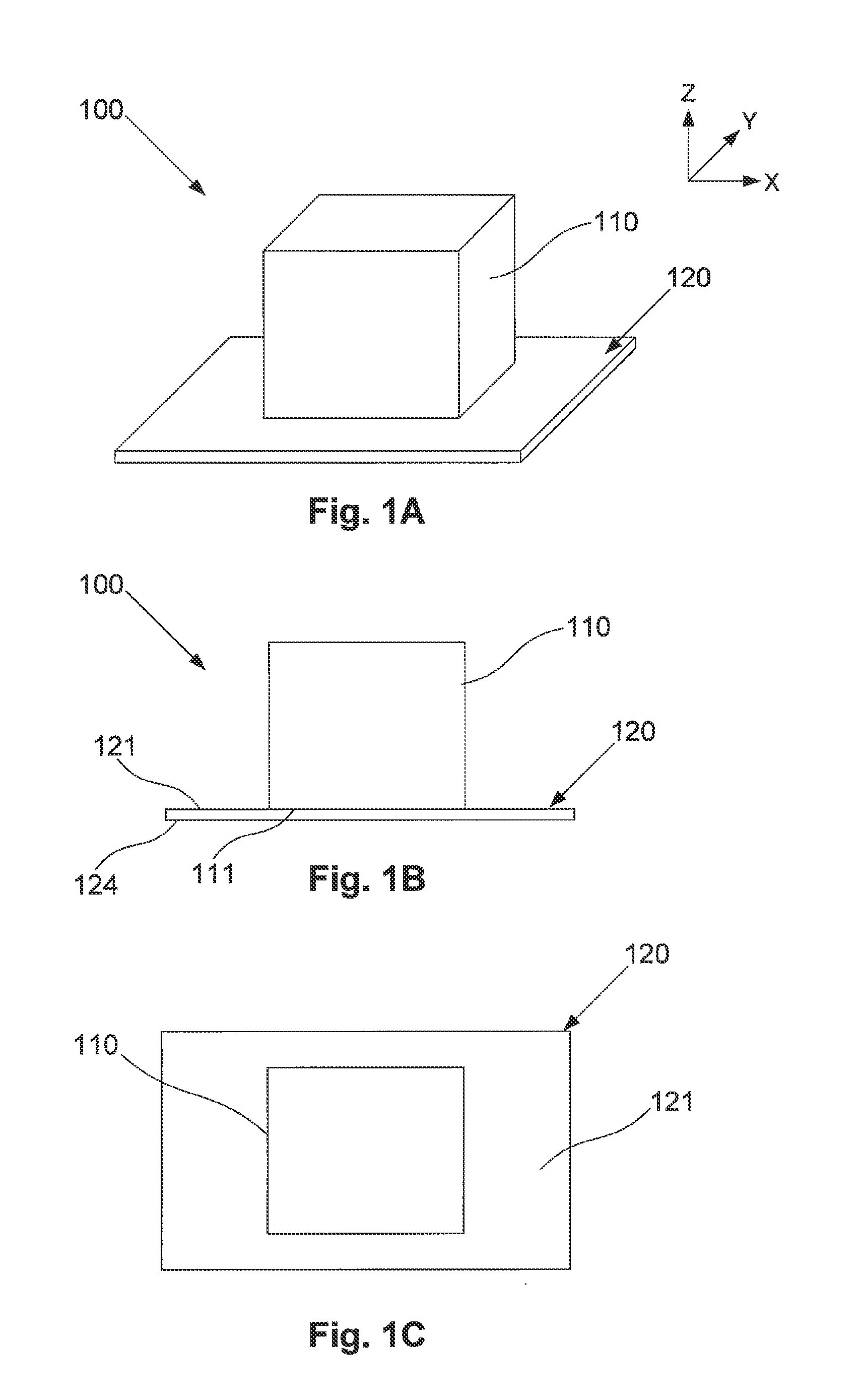
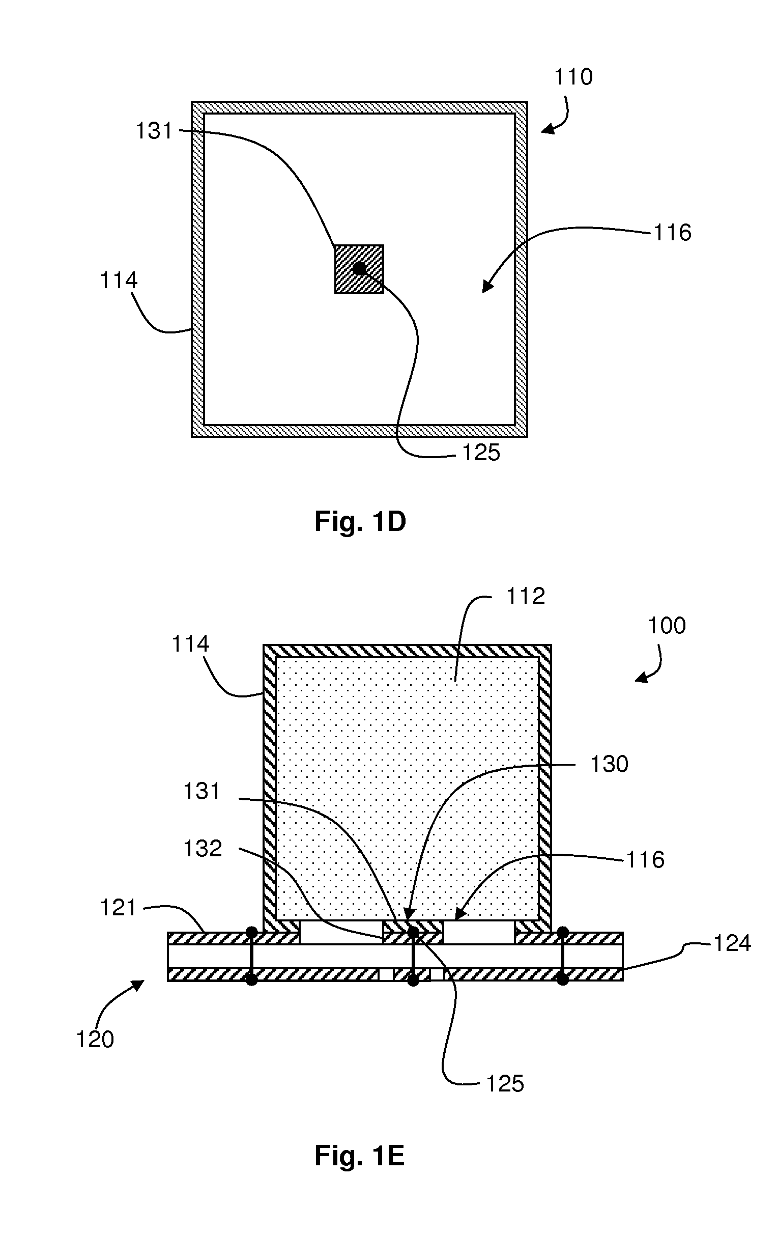
[0044]An example of a multi-mode filter will now be described with reference to FIGS. 1A to 1F.

[0045]In this example, the filter 100 includes a resonator body 110, a substrate 120 and a coupling structure 130. The coupling structure 130 consists of a single conductive patch element 131 extending adjacent at least part of a surface 111 of the resonator body 110. As will be described in greater detail below, the coupling structure 130 allows for coupling of signals to or from the resonator body 110 and, depending on the coupling structure 130 and the shape of the resonator body 110, may provide coupling to a plurality of resonance modes of the resonator body.

[0046]In use, a signal can be supplied to or received from the conductive patch element 131. In a suitable configuration, this allows a signal to be filtered to be supplied to the resonator body 110 for filtering, or can allow a filtered signal to be obtained from the resonator body, as will be described in more detail below.

[0047...


PUM

PropertyMeasurementUnit
energyaaaaaaaaaa
conductiveaaaaaaaaaa
electric fieldaaaaaaaaaa

Abstract

A cavity filter, including a dielectric resonator structure comprising a piece of dielectric material having a shape such that it can support a first resonant mode and a second resonant mode which is substantially degenerate with the first resonant mode; and a coupling structure for exciting a resonant mode within the piece of dielectric material or extracting energy from a resonant mode within the piece of dielectric material; wherein the coupling structure consists of a single patch element in contact with a surface of the piece of dielectric material, the patch element being arranged to couple directly to said first and second resonant modes simultaneously.

Description

CROSS REFERENCE TO RELATED APPLICATIONS[0001]The present application is related to and claims the benefit of Australian Provisional Patent Application No. 2011903389, filed Aug. 23, 2011 and U.S. Provisional Patent Application No. 61 / 531,277, filed Sep. 6, 2011, both of whose disclosures are hereby incorporated by reference in their entirety into the present disclosure.TECHNICAL FIELD [0002]The present invention relates to filters, and in particular to a filter including a resonator body for use, for example, in frequency division duplexers for telecommunication applications.BACKGROUND[0003]The reference in this specification to any prior publication (or information derived from it), or to any matter which is known, is not, and should not be taken as an acknowledgment or admission or any form of suggestion that the prior publication (or information derived from it) or known matter forms part of the common general knowledge in the field of endeavour to which this specification relate...

Claims


Application Information

Patent Timeline
Patent Type & Authority Applications(United States)
IPC IPC(8): H01P1/20
CPCH01P1/2088Y10T29/49016H01P7/105H01P1/2086H01P1/2002
Inventor HENDRY, DAVID ROBERTCOOPER, STEVEN JOHNKENINGTON, PETER BLAKEBOROUGH
Owner MESAPLEXX
Learn More