Flow cytometer droplet formation system

a flow cytometer and droplet technology, applied in the field of droplet flow cytometers, can solve the problems of difficult to achieve practicable processing rate, difficult to deal, particularly difficult to achieve processing rate, etc., and achieve the effect of enhancing the amplification of the oscillation and increasing the performance of the droplet flow cytometer

Inactive Publication Date: 2005-03-01
UNIV OF WASHINGTON
View PDF60 Cites 67 Cited by
  • Summary
  • Abstract
  • Description
  • Claims
  • Application Information

AI Technical Summary

Benefits of technology

The present invention involves a number of improvements which are applicable to a flow cytometer droplet system. These improvements each offer independent advantages and may be combined synergistically to produce a great increase in the performance of droplet flow cytometers. The preferred embodiment involves a piezoelectric oscillator contained within the sheath fluid above a continuously converging nozzle container. This nozzle container acts to amplify the oscillations which are directly and directionally coupled to the sheath fluid. Further, the location of the substance introduction tube may be adjusted within a convergence zone so as to vary the rate at which the substance is introduced relative to the rate at which the sheath fluid is introduced to maintain optimal conditions. In addition, a replaceable nozzle tip is fit within an edge insert and sealed on its outer surface so as to maintain laminar flow and enhance the amplification of the oscillation throughout the converging nozzle body. As a result of the combination of these various features, the present invention not only achieves practical processing at frequencies of many multiples of typical prior art devices, but it also achieves these processing rates at oscillation powers which are several orders of magnitude less than those typically utilized.

Problems solved by technology

One of the facets of these systems which has been particularly challenging, however, is the aspect of controlling the drop formation.
As to this aspect it has not only been difficult to practically achieve processing rates of much more than 40 kilohertz, it has also been difficult to deal with the incidents of using relatively high power to drive the oscillators involved.
Their operation as continuous flow devices rather than droplet formation devices makes much of the understandings available in that field inapplicable to the challenges and problems faced in flow cytometry droplet formation systems.
To some degree the challenges for droplet formation may be the result of the fact that although drop formation has been modeled with significant theoretical detail, in practice it still remains a somewhat empirical subject.
A number of “advances” in this field have even proved to be either unnecessary or unworkable in practice.
Unfortunately, this relatively high voltage not only results in a need for more robust circuitry, but it also has the undesirable practical consequence of resulting in undesirable electromagnetic emissions.
These emissions can impact the sensitivity of the flow cytometer or other nearby equipment.
Further, as the desire for higher processing frequencies is pursued, this problem is compounded.
Yet another problem practically encountered in this field was the challenge of resonances existing within the nozzle assembly.
Again, this appears to have simply been accepted as a necessary incident of workable systems and may have resulted in an attitude among those having ordinary skill in the art that it was not practical to vary frequency without unacceptable changes in the performance of the entire system.
There also seems to have been some confusion as to the appropriate way to apply the droplet forming oscillations.
An even more paradoxical situation exists with respect to the problem of maintaining laminar flow within the nozzle system of a droplet flow cytometer.
Although those having ordinary skill in this field have known for years that maintaining laminar flow was desirable, until the present invention, practical systems utilizing replacement tips have not been optimally designed so as to achieve the goal of truly laminar flow.
Again, such designs seem to present almost a paradox in that they obviously are not optimum from perspective of a goal which has long been known as those having ordinary skill in the art.
Yet another problem encountered in this field is the need to vary parameters to optimize actual conditions encountered in processing.
Again theory and practice did not mix well.
Solutions, however, had either been perceived as unlikely or not been recognized even though the implementing elements had long been available.
This may also have been due to the fact that those having ordinary skill in the art may not have fully appreciated the nature of the problem or may have been due to an actual misunderstanding of the physical mechanisms involved.
These appear to have included the misunderstanding that actually moving the nozzle was the proper way to induce the droplet forming oscillations and the simple failure to realize that it was possible to coordinate the desire for replaceable nozzle tips with the desire for laminar flow within the flow cytometer nozzle assembly.

Method used


Image

  • Flow cytometer droplet formation system
  • Flow cytometer droplet formation system
  • Flow cytometer droplet formation system

Examples


Embodiment Construction

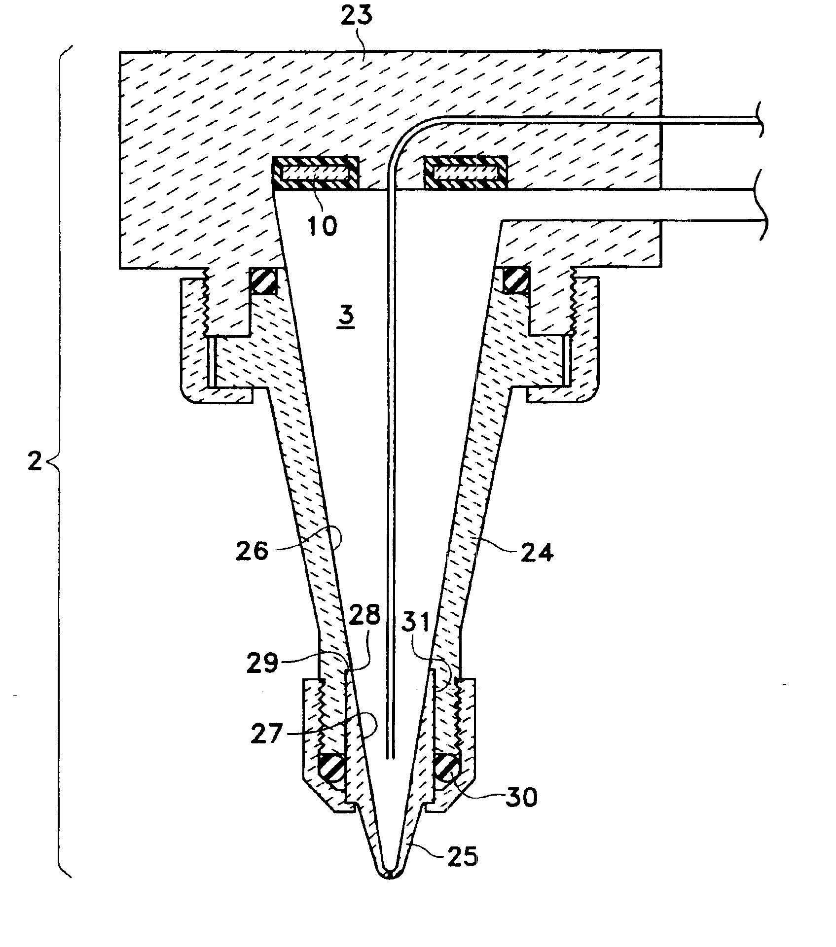
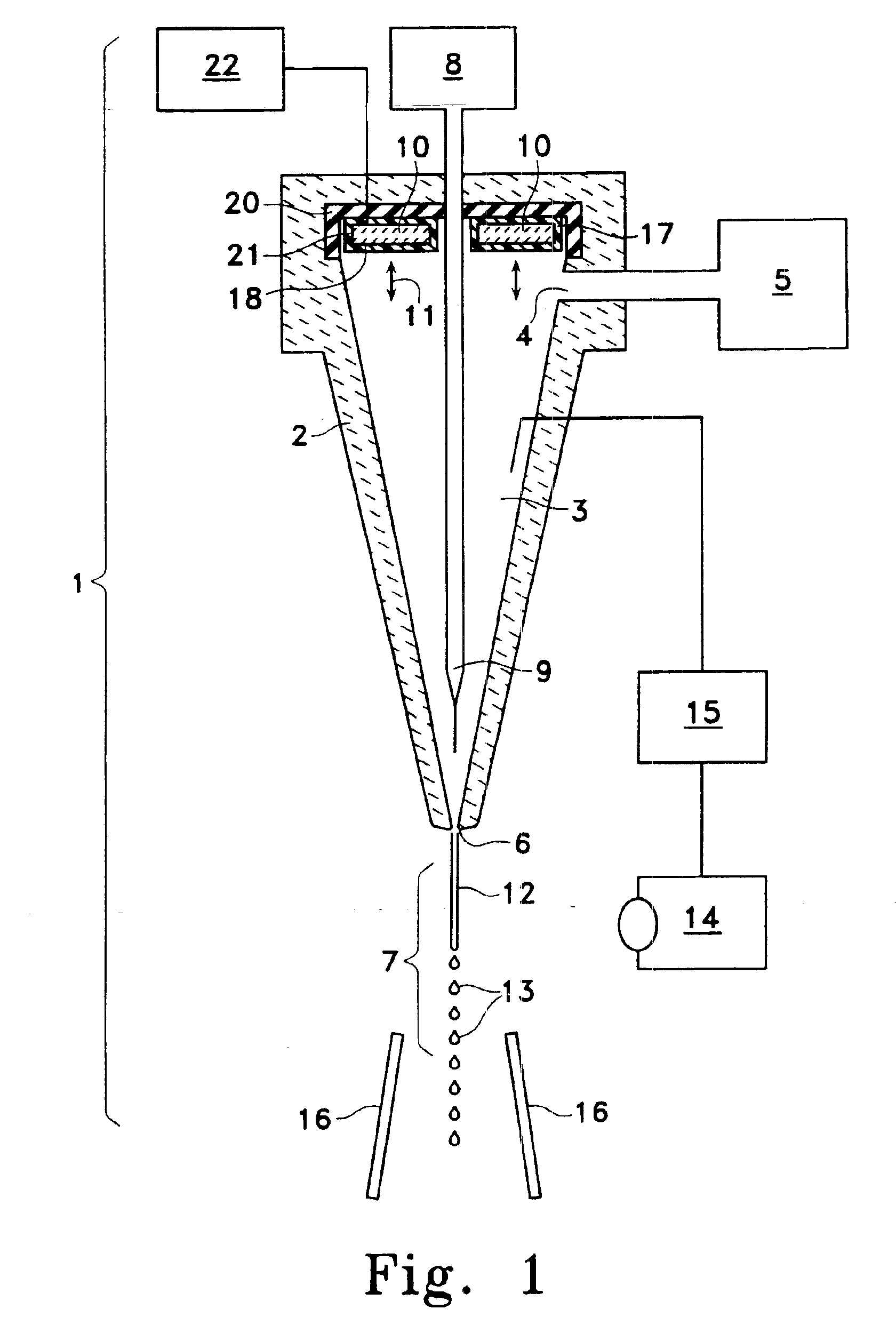
As mentioned, the present invention involves an improved flow cytometer droplet nozzle system which incorporates a variety of features. As shown in FIG. 1, the flow cytometer system (1) involves nozzle container (2) which establishes nozzle volume (3). Nozzle volume (3) is supplied a liquid by sheath fluid port (4) which acts to introduce a sheath fluid from some sheath reservoir (5). During operation, the sheath fluid flows through nozzle container (2) and out nozzle exit (6) into free fall area (7).

Since the sheath fluid is typically an unreactive substance such as a saline fluid and is an analytically transparent, it has introduced within it some desirable substance such as cells or parts of cells or other items. This substance is maintained in substance reservoir (8) and is introduced to nozzle volume (3) through substance introduction port (9). Through hydrodynamic focusing, the substance flows and is separated into single cell units within the sheath fluid and exits at nozzle ...


PUM

PropertyMeasurementUnit
alternating voltage amplitudeaaaaaaaaaa
voltage amplitudeaaaaaaaaaa
droplet formation frequenciesaaaaaaaaaa

Abstract

A droplet forming flow cytometer system allows high speed processing without the need for high oscillator drive powers through the inclusion of an oscillator or piezoelectric crystal within the nozzle volume and directly coupled to the sheath fluid. The nozzle contain converges so as to amplify unidirectional oscillations which are transmitted as pressure waves through the nozzle volume to the nozzle exit so as to form droplets from the fluid jet. The oscillator is directionally isolated so as to avoid moving the entire nozzle container so as to create only pressure waves within the sheath fluid. A variation in substance concentration is achieved through a movable substance introduction port which is positioned within a convergence zone to vary the relative concentration of substance to sheath fluid while still maintaining optimal laminar flow conditions. This variation may be automatically controlled through a sensor and controller configuration. A replaceable tip design is also provided whereby the ceramic nozzle tip is positioned within an edge insert in the mozzle body so as to smoothly transition from nozzle body to nozzle tip. The nozzle tip is sealed against its outer surface to the nozzle body so it may be removable for cleaning or replacement.

Description

I. BACKGROUND OF THE INVENTIONGenerally this invention relates to droplet flow cytometers such as are used for the analysis and sorting of substances contained within separate droplets. Specifically the invention relates to aspects of such systems which act to form regular droplets after exit from a nozzle orifice.Droplet flow cytometers have been in clinical and research use for many years. Basically, the systems act to position small amounts of a substance within individual droplets of a sheath fluid. These droplets can be made uniform by utilizing an oscillator which emits a predominant frequency. These oscillations are usually applied to the nozzle container. Since droplet flow cytometry is heavily utilized in both research and clinical environments, such systems have been the subject of much refinement. One of the facets of these systems which has been particularly challenging, however, is the aspect of controlling the drop formation. As to this aspect it has not only been diff...

Claims


Application Information

Patent Timeline
Patent Type & Authority Patents(United States)
IPC IPC(8): G01N15/14
CPCG01N15/1404G01N2015/1406Y10T436/25375Y10T436/2575G01N2015/1409
Inventor DEN ENGH, GER VAN
Owner UNIV OF WASHINGTON
Why Eureka
Try Eureka