Dynamic channel estimation apparatus, systems and methods

a technology of dynamic channel and estimation apparatus, applied in the field of apparatus, systems and methods associated with wireless communication technology, can solve problems such as the inability to measure distance and other problems

Active Publication Date: 2013-02-28
TEXAS INSTR INC
View PDF4 Cites 35 Cited by
  • Summary
  • Abstract
  • Description
  • Claims
  • Application Information

AI Technical Summary

Benefits of technology

[0013]N-determining factors include the length D1 of a path between the two wireless stations as determined by TOF measurements. It is noted that D1 is related to the TOF measurements by the constant C, the speed of light traveling through a selected medium. Therefore, references herein to N as a function of D1 are equally applicable to N as a function of TOF. N is also dependent upon one or more received signal strength values (collectively, RSS(1)) measured at the first wireless station and corresponding to transmissions originating at the second wireless station.
[0014]In some embodiments, the first wireless station takes multiple RSS(1) measurements of radio frequency (RF) energy received from the second wireless station. The first wireless station may act upon one or more averages of RSS(1) measurements or other statistical accumulations of RSS(1) over determined periods of time to calculate N dynamically. Embodiments herein determine N from RSS(1), D1, and / or known path gain / loss parameter values. The latter parameters may include a short-range empirical RSS value corresponding to a reference path length, values of path gain parameters including transmit power levels and antenna gain values, and / or path gain coefficient constants.

Problems solved by technology

In these cases, TOF measurements to determine distance may not be possible

Method used


Image

  • Dynamic channel estimation apparatus, systems and methods
  • Dynamic channel estimation apparatus, systems and methods
  • Dynamic channel estimation apparatus, systems and methods

Examples


Embodiment Construction

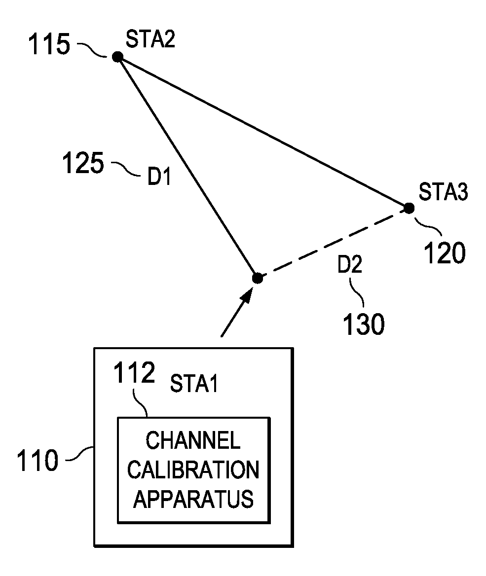
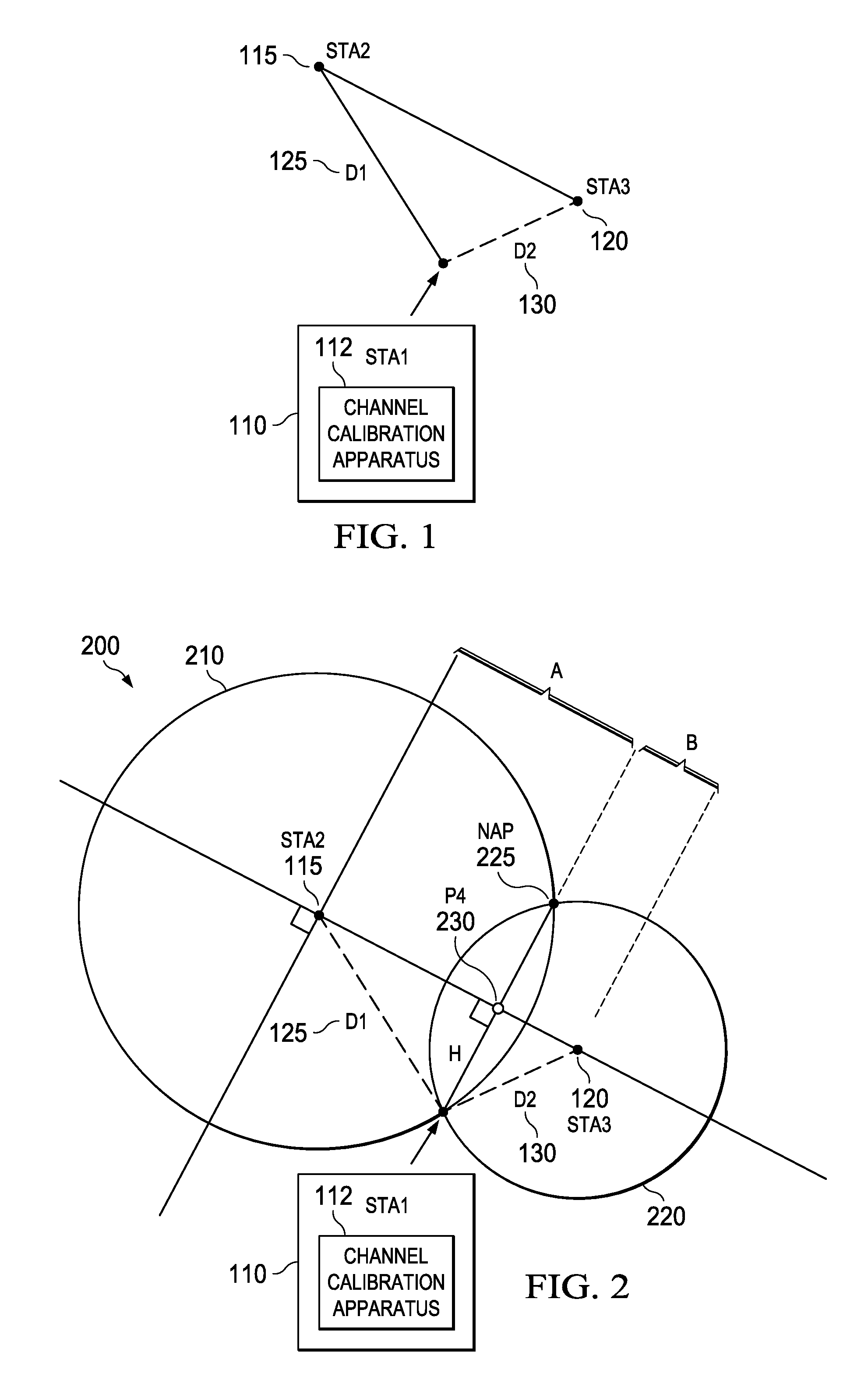
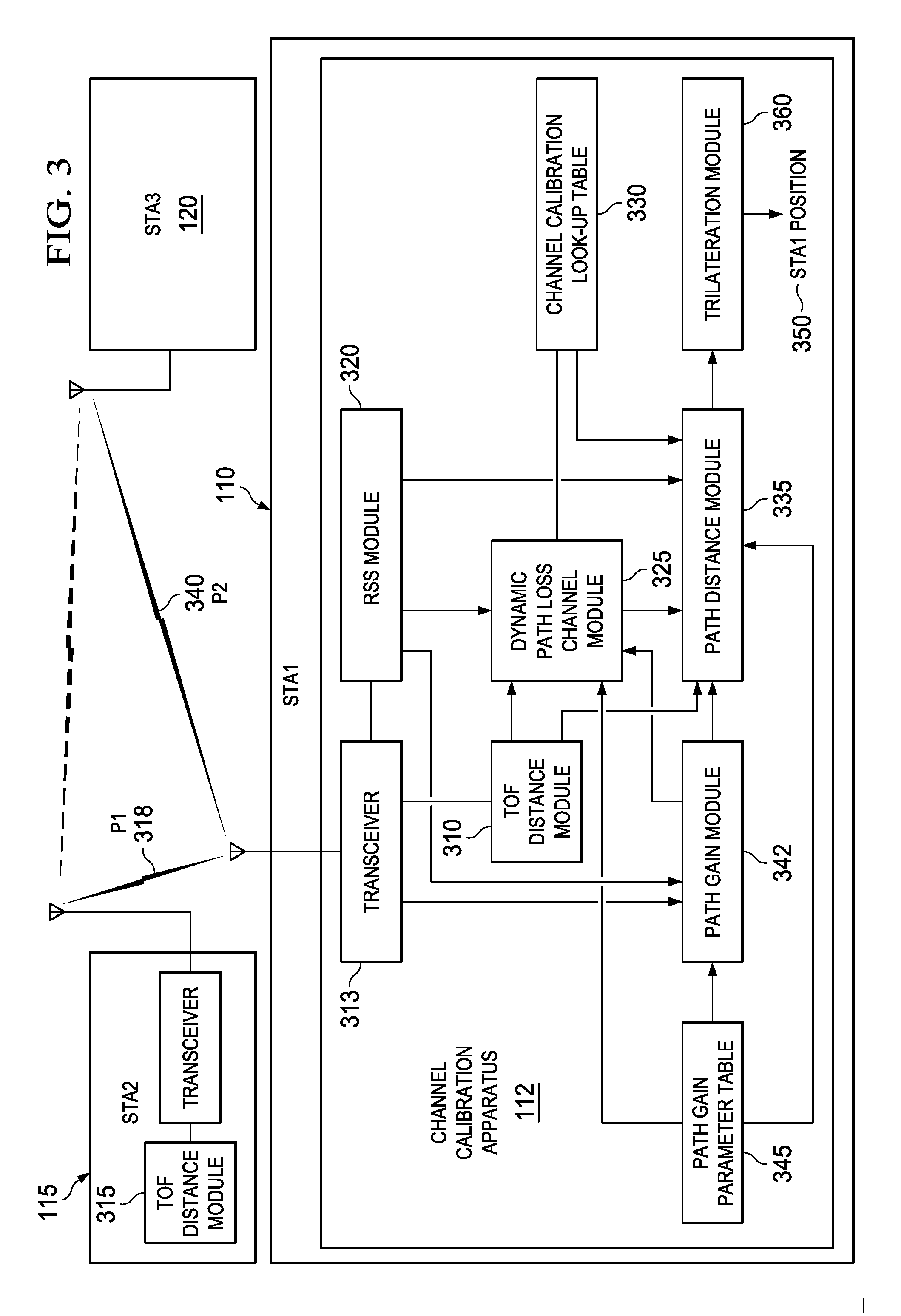
[0017]FIG. 1 is a system diagram of a wireless station (e.g., the first wireless station STA1110) incorporating a wireless channel calibration apparatus 112 according to various example embodiments of the invention. The STA1110 is positioned relative to two additional wireless stations (e.g., the second wireless station STA2115 and the third wireless station STA3120). STA2115 and STA3120 may, but need not be, APs. In some environments, particularly indoor environments, a user of STA1110 may wish to determine his / her coordinate location in the absence of a GPS or other navigation signal.

[0018]Some wireless geometries may lend themselves to determining the position of STA1110 if the position coordinates of STA2115 and the STA3120 are known. STA1110 may acquire STA2115 and STA3120 position coordinates through various techniques. Each AP in a multi-AP network may, for example, store a table of position coordinates corresponding to the locations of other APs in the network. The table of ...


PUM


Abstract

Apparatus, systems, and methods disclosed herein operate to calibrate path loss parameters corresponding to a communication channel between wireless stations, including a path loss exponent. A time-of-flight (TOF) associated with packet transmissions traversing a path between a first wireless station and a second wireless station is measured. A path length D1 corresponding to the path is calculated from the TOF measurements. One or more received signal strength (RSS) measurements corresponding to the packet transmissions are then made at the first wireless station. The path loss exponent associated with the path is calculated from D1 and the RSS measurements. Some embodiments may also measure RSS values associated with transmissions from a third wireless station. The latter measurements may be used in conjunction with the previously-determined path loss exponent to derive an unknown transmission path length between the first and third wireless stations. The latter path length may be used together with other known station geometry to determine the coordinate position of the first wireless station.

Description

TECHNICAL FIELD[0001]Embodiments described herein relate to apparatus, systems and methods associated with wireless communication technology, including structures and methods associated with signal propagation characterization and position localization.BACKGROUND INFORMATION[0002]Personal mobile communication (PMC) devices such as smart phones and Internet tablet computers are becoming increasingly ubiquitous. One factor driving the popularity of these devices is their use in geolocation and navigation. Built-in Global Positioning System (GPS) apparatus capture signals from GPS satellites and calculate a PMC device coordinate position from the signals. Position accuracies within 15 to 30 feet may be achieved. GPS received signal strength and frequencies largely render the GPS system line-of-sight and suitable for outdoor use, however.[0003]There is an unserved need for location positioning and distance estimation within buildings. Examples include finding a friend or associate at a ...

Claims


Application Information

Patent Timeline
Patent Type & Authority Applications(United States)
IPC IPC(8): H04W24/00
CPCH04W24/02H04W24/08H04W64/00G01S5/021G01S5/14H04B17/318H04L43/50H04W24/00H04B17/11H04B17/21H04J3/14
Inventor ESTEVEZ, LEONARDO WILLIAMWATERS, DERIC
Owner TEXAS INSTR INC
Why Eureka
Try Eureka