Dynamically channelizable packet transport network

a dynamic channel and packet transport technology, applied in the field of packet transport networks, can solve the problems of inefficient dedicated point-to-point link network architecture, inefficient bursty packet traffic, and inability to carry other potential billable traffic, so as to achieve the network capacity utilization efficiency of packet-layer, reduce the cost of deploying and operating the network infrastructure, and reduce the effect of total network capacity usag

Active Publication Date: 2008-02-19
OPTIMUM COMM SERVICES +1
View PDF18 Cites 40 Cited by
  • Summary
  • Abstract
  • Description
  • Claims
  • Application Information

AI Technical Summary

Benefits of technology

[0022]The present invention enables to provide multiple independent, i.e. private-like, site-to-site mesh subnetworks for multi-sited clients over a common shared network infrastructure, without requiring neither per-client-dedicated switches nor dedicated site-to-site connections. The invention thereby enables providing the desired connectivity, i.e. guaranteeing a required minimum bandwidth while providing the ability to dynamically utilize all the available bandwidth, among the client sites with minimized total network capacity usage. Thus the invention effectively combines the QoS of dedicated L1 point-to-point circuits with the network resource usage efficiency of L2 / L3 packet-switching. The invention accomplishes that objective by providing means for provisioning flexible logical L1 topologies among a set of client sites, and by applying packet-switching within such isolated client subnetworks. The result is a set of client-specific subnetworks, called in the industry as virtual private networks (VPNs), provided over a common, L1-shared network infrastructure that operate independent of each other, and that require the theoretical minimum physical network capacity to provide the required connectivity among the sites of each subnetwork. The invention fully achieves the network capacity usage efficiency of packet-layer (L2 / L3) VPNs, but it does not require the complex packet-layer processing switching systems required for packet-layer VPNs that substantially increase the cost of deploying and operating the network infrastructure.
[0023]The L1-separation of different VPNs provided by the present invention allows simplified, yet more efficient and feature-rich, packet-forwarding to be used within the individual packet-switched VPNs. Thus, rather than requiring more complex and expensive packet-switching systems, as do the conventional packet-layer VPNs that do not provide L1-separation between different VPNs and thus require deeper upper layer protocol processing to provide isolation among different VPNs, the present invention enables using more cost-efficient and scalable packet-switching schemes. Due to its novel dynamic L1 channelization within each multi-site VPN that provides direct, bandwidth-optimized L1-channels between the VPN access sites, the present invention requires packet-layer processing only for the VPN access interfaces, but not for the high-bit-rate backbone interfaces. Furthermore, a preferred embodiment of the present invention uses SDH / SONET virtual concatenation based L1 separation and channelization, thus providing flexible allocation of network capacity at L1.
[0024]The invention is based on dynamically L1-channelizable packet transport buses, a set of which can be configured over a standard, e.g. SDH / SONET / WDM, network infrastructure to provide a desired connectivity among a set of client sites. For instance, with such dynamically L1-channelizable buses it is possible to provide out of a group of sites direct connections between such sites that need most mutual traffic exchange bandwidth, while connecting sites that need less mutual traffic exchange bandwidth through an intermediate forwarding point to optimize network resource utilization. Such a dynamically L1-channelizable packet transport bus, the subject matter of the present invention, provides a pool of network capacity for transport of packets from a set of source nodes to the destination node of the bus. The bus of the present invention provides a L1 channel with adjustable bandwidth from each of its source nodes to its destination node, and incorporates a real-time-dynamic control plane that periodically optimizes the allocation of the bus capacity pool among the source node specific channels based on the real-time packet-traffic-loads from the sources toward the destination of the bus, thereby continuously maximizing the data throughput of the network for the part of that bus.

Problems solved by technology

Such a network architecture based on non-shareable connections is however inefficient for bursty packet traffic, since the bandwidth reserved for the dedicated point-to-point connections is wasted when not used for communication between the two sites at the two ends of the point-to-point connection; none of the point-to-point link bandwidth can be used to carry other potential billable traffic even when not needed by traffic between the two sites connected by the point-to-point link.
When guaranteed connectivity is needed among more than two sites, such as POPs of an ISP, the dedicated point-to-point link based network architecture is even more inefficient.
Obviously, the dedicated link-based network architecture is the more inefficient the greater the number of sites to be interconnected is.
It is clear that ensuring QoS via such per-subscriber-dedicated and redundant link and switch based communications networks looses the economical advantage of providing connectivity over multi-subscriber shared public Internet, and thus does not improve the cost-efficiency of packet networking.
Providing the required QoS per each client network by using shared L1 / L0 connections and packet-switches and reserving adequate capacity at the packet layer rather than by using per-client-dedicated connections and switches may enable finer granularity of capacity allocation, but that comes with the cost of significantly more complex and costlier packet-layer network elements.
Thus, the L2 / L3 VPNs also appear to create another trade-off between performance and cost advantage, and do therefore not produce a clear cost-efficiency improvement.
To summarize, while networks based on conventional dedicated L1 point-to-point circuits are often prohibitively inefficient for bursty packet traffic, conventional L2 (or above) shared packet-switched networks are not able to provide deterministic QoS without compromising the bandwidth efficiency of packet-switching, by reserving capacity for the connections requiring guaranteed throughput, and without making the packet-switched network infrastructure more costlier.

Method used


Image

  • Dynamically channelizable packet transport network
  • Dynamically channelizable packet transport network
  • Dynamically channelizable packet transport network

Examples


Embodiment Construction

[0032]The invention is described herein first by illustrating the novel concepts via a more detailed discussion of the drawings, and then by providing specifications for a currently preferred embodiment of the invention.

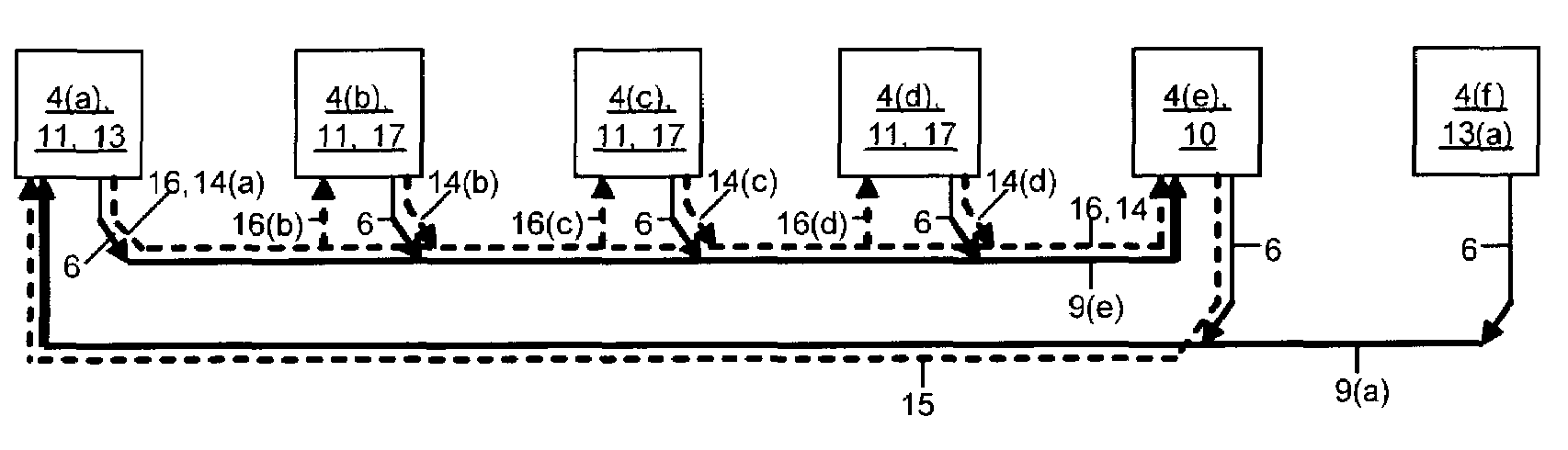
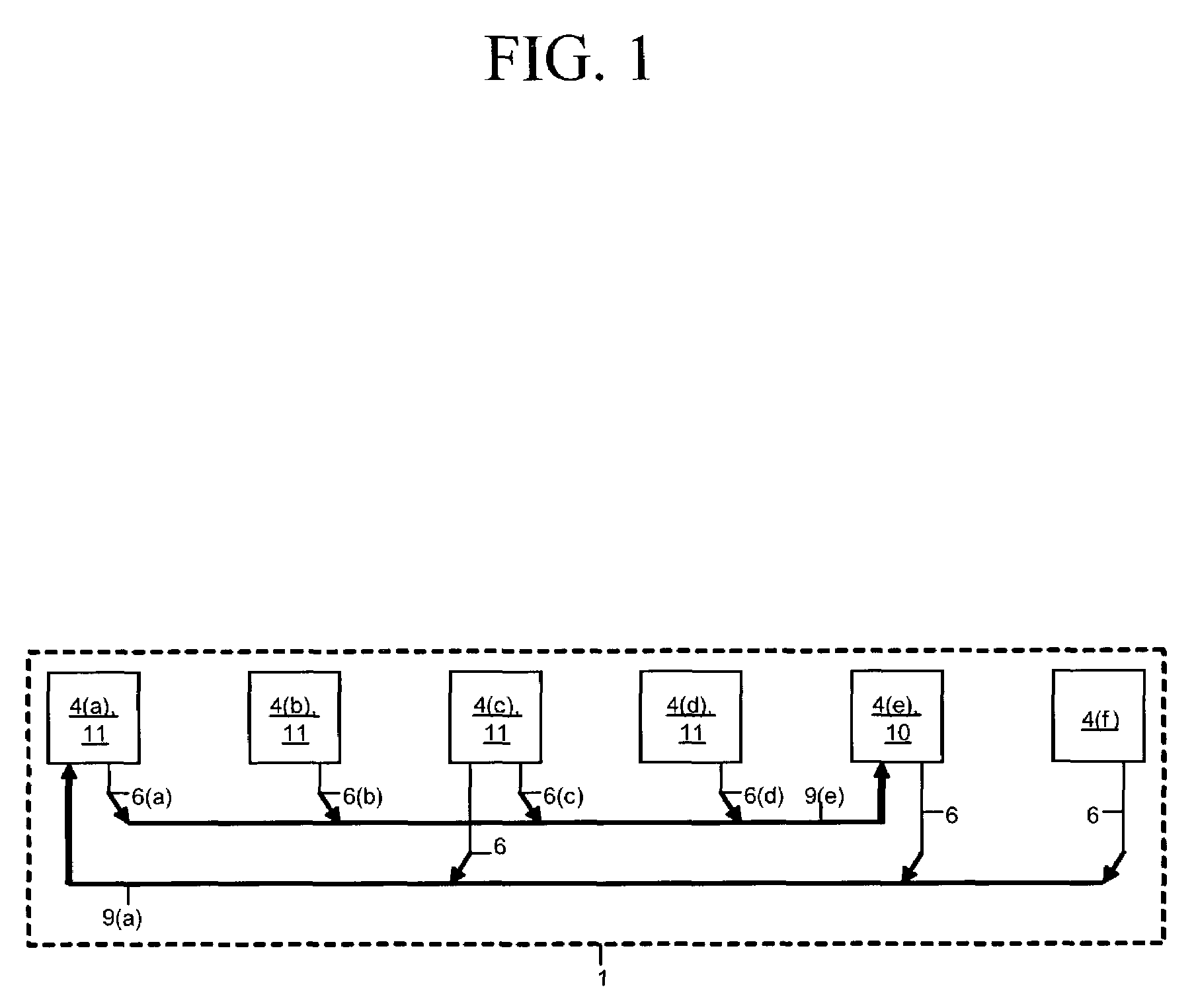
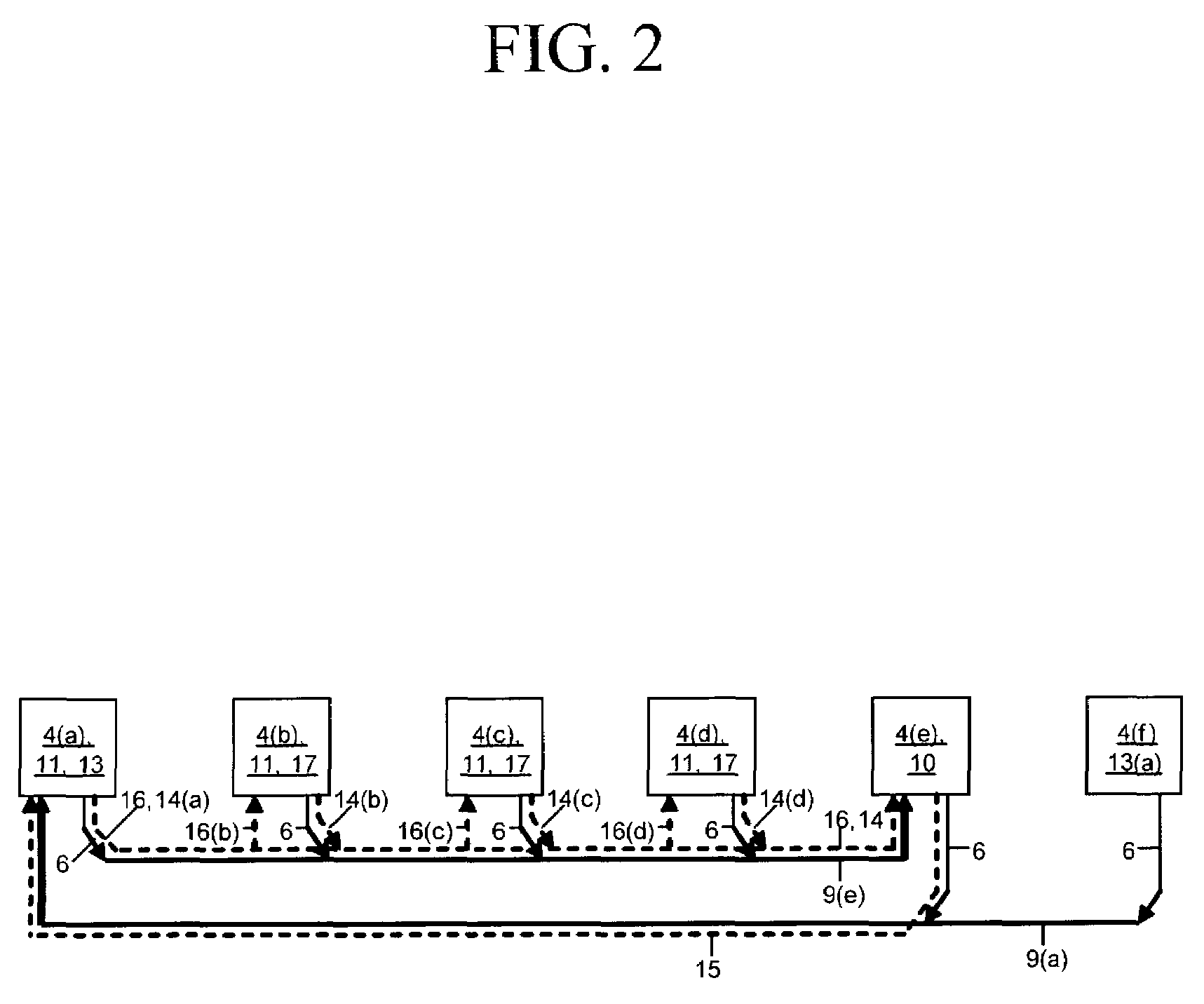
[0033]Symbols and notations used in the drawings:[0034]Lines and arrows between nodes, the nodes drawn as boxes, in the drawings represent a logical communication path, and may physically consist of one or more physical wires. When no direction is indicated, a line between nodes or boxes in the network diagrams presents a two-directional communication path.[0035]Solid arrows indicate a communications signal i.e. data traffic flow. Gapped arrows indicate control information flow.[0036]Bold lines indicate bussed communication paths, i.e. communication paths shareable by traffic flows from either various sources or to various destinations within the reach of the bus.[0037]Lines or arrows crossing in the drawings are decoupled unless otherwise marked. Arrows ending into ...


PUM


Abstract

A communications network for transporting data packets among L2 / L3 nodes based on dynamically L1-channelizable multi-source buses. The dynamic channelization of a packet transport bus among source-node-specific L1 connections is managed by a bus control process, which periodically optimizes the allocation of bus capacity pool among the source nodes based on real-time bus capacity demand figures by the source nodes of the bus. The invention provides means for real-time dynamic, traffic load adaptive allocation of transport network capacity to continuously maximize the data throughput of the transport network for dynamic packet traffic, such as Internet traffic.

Description

CROSS-REFERENCES TO RELATED APPLICATIONS[0001]The subject matter of this application is related to and makes references to the following patent applications:[0002][1] Co-pending U.S. utility patent application Ser. No. 09 / 938,014, filing date Aug. 24, 2001, by Mark Henrik Sandstrom, entitled “A System and Method for Maximizing the Traffic Delivery Capacity of Packet Transport Networks via Real-time Traffic Pattern Based Optimization of Transport Capacity Allocation”;[0003][2] U.S. provisional patent application Ser. No. 60 / 347975, filing date Oct. 19, 2001, by Mark Henrik Sandstrom, entitled “Intelligent Transport Network”;[0004][3] U.S. provisional patent application Ser. No. 60 / 356503, filing date Feb. 11, 2002, by Mark Henrik Sandstrom, entitled “Real-time Control-Plane for Maximizing Billable-Traffic-Throughput of Packet Transport Networks”;[0005][4] Co-pending U.S. utility patent application Ser. No. 10 / 170,260, filing date Jun. 13, 2002, by Mark Henrik Sandstrom, entitled “Inp...

Claims


Application Information

Patent Timeline
Patent Type & Authority Patents(United States)
IPC IPC(8): H04J3/16H04L12/417
CPCH04L12/40169H04L12/417
Inventor SANDSTROM, MARK HENRIK
Owner OPTIMUM COMM SERVICES
Why Eureka
Try Eureka