Pneumatically-driven jetting valves with variable drive pin velocity, improved jetting systems and improved jetting methods

Inactive Publication Date: 2013-02-28
NORDSON CORP
View PDF3 Cites 27 Cited by
  • Summary
  • Abstract
  • Description
  • Claims
  • Application Information

AI Technical Summary

Benefits of technology

[0015]In another embodiment, the solenoids can be controlled to provide a desired overlap time period during which compres

Problems solved by technology

Given that the needle velocity is limited to a relatively narrow range, the range of

Method used


Image

  • Pneumatically-driven jetting valves with variable drive pin velocity, improved jetting systems and improved jetting methods
  • Pneumatically-driven jetting valves with variable drive pin velocity, improved jetting systems and improved jetting methods
  • Pneumatically-driven jetting valves with variable drive pin velocity, improved jetting systems and improved jetting methods

Examples


Embodiment Construction

[0027]Subheadings are provided in some sections below to help guide the reader through some of the various embodiments, features and components of the invention.

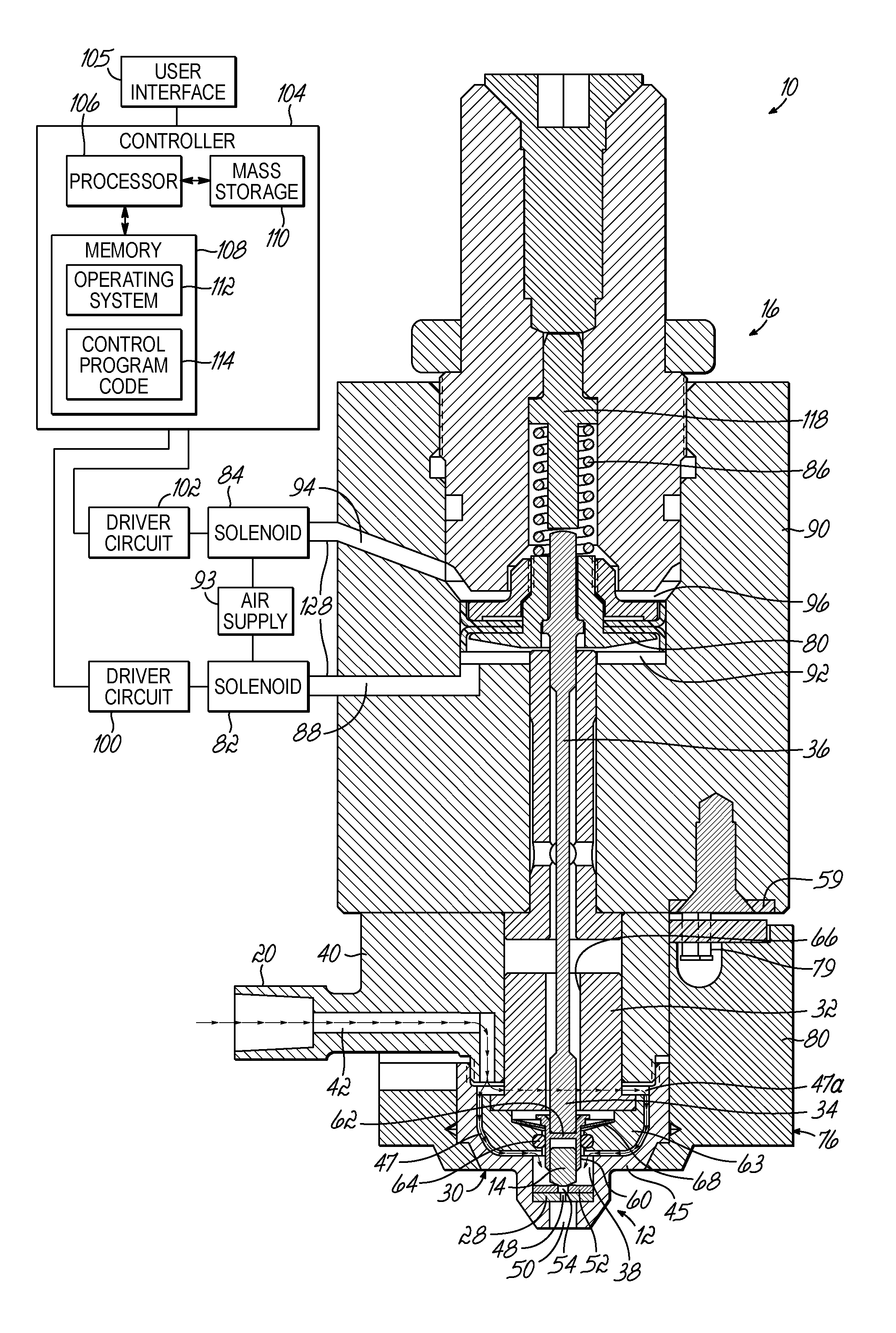
[0028]Generally, the embodiments of the invention relate to a jetting valve that uses first and second solenoid valves to operate a pneumatic piston of an electro-pneumatic actuator, which precipitates movement of a valve element for opening and closing the jetting valve. Independent air lines are coupled with top and bottom chambers of the pneumatic piston. The first and second solenoid valves independently control the air pressure supplied to the top and bottom chambers of a pneumatic piston. The first solenoid valve is used to open the jetting valve and the second solenoid valve is used to close the jetting valve. The velocity of the needle that is fixed to the piston to cause the valve to open and close can be varied by changing the amount of time that the action of the second solenoid valve in supplying compressed air t...


PUM

PropertyMeasurementUnit
Timeaaaaaaaaaa
Pressureaaaaaaaaaa
Viscosityaaaaaaaaaa

Abstract

An improved pneumatic jetting valve includes a housing with first and second chambers. A pneumatic piston is enclosed between the chambers. First and second solenoid valves are configured to respectively supply air pressure to the chambers and to exhaust the chambers. A controller is operable to regulate the pressurization and venting of the chambers. The controller controls the timing of control signals for the first and second solenoid valves to control the overlap time during which both the first and second chambers are pressurized. By controlling this overlap time, the controller controls the speed of the drive pin of the jetting valve and thereby the speed at which the valve closes to jet a droplet of material. This allows a valve speed to be selected that is most appropriate for the viscosity of the material being jetted. Numerous new methods for utilizing the improved jetting valve and system are disclosed.

Description

CROSS-REFERENCE TO RELATED APPLICATIONS[0001]This application is related to application Ser. No. ______, filed on even date herewith, and entitled “MODULAR JETTING DEVICES” (Attorney Docket No. NOR-1414US), which is hereby incorporated by reference herein in its entirety.BACKGROUND[0002]The invention relates generally to the jetting of fluid materials and, in particular, to electro-pneumatic jetting valves, jetting systems and improved jetting methods.[0003]Jetting valves are used in the electronic packaging assembly to jet minute dots of a fluid material onto a substrate. Numerous applications exist for jetting valves that jet fluid materials such as underfill materials, encapsulation materials, surface mount adhesives, solder pastes, conductive adhesives, and solder mask materials, fluxes, and thermal compounds. As the type of fluid material changes, the jetting valve must be adapted to match the fluid material change. A “jetting valve” or “jetting device” is a device which ejects...

Claims


Application Information

Patent Timeline
IPC IPC(8): F17D3/00B05C11/10B05D1/02B05C5/00
CPCB05C5/0225B05C11/1002B05C11/1028B05C11/1034Y10T137/0318Y10T137/86405B05C5/02B05D1/26H05K3/10
Inventor AHMADI, MANIFISKE, ERIKMAIORCA, PHILIP PAULQUINONES, HORATIOWRIGHT, ROBERT JAMES
Owner NORDSON CORP
Why Eureka
Try Eureka