Plane Wave Generation Within A Small Volume Of Space For Evaluation of Wireless Devices

a wireless device and small space technology, applied in the field of plane wave creation, anechoic chamber, spatial channel model, over the air testing of wireless devices, can solve the problems of large and expensive structure of the anechoic chamber

Active Publication Date: 2013-02-28
AZIMUTH SYSTEMS
View PDF20 Cites 25 Cited by
  • Summary
  • Abstract
  • Description
  • Claims
  • Application Information

AI Technical Summary

Benefits of technology

[0017]An advantage associated with at least some aspects is the creation of user-specified propagating plane waves in a smaller anechoic chamber. For example, such plane waves might be created in a test zone that is in the near field of the test-equipment antennas. Current anechoic chambers typically require distances of greater than four wavelengths between test-equipment antennas and the test zone. Aspects associated with the present invention can enable operation at smaller distances, e.g., less than four, three or two wavelengths, and even at a distance of approximately one wavelength. Moreover, at least some aspects allow strong multiple interactions between the chamber walls and the test-equipment antennas. With the DUT placed in the test zone of a small anechoic chamber tests that would have previously required a large anechoic chamber may be performed. For example, total isotropic sensitivity (TIS) tests, total radiated power (TRP) tests, and throughput measurements using advanced spatial channel models such as described in CTIA—The Wireless Association, “Test Plan for Mobile Station Over the Air Performance Method of Measurement for Radiated RF Power and Receiver Performance,” Revision Number 3.1, January 2011 can be performed.

Problems solved by technology

As a consequence, the anechoic chamber is a large and expensive structure that may measure several meters across.

Method used


Image

  • Plane Wave Generation Within A Small Volume Of Space For Evaluation of Wireless Devices
  • Plane Wave Generation Within A Small Volume Of Space For Evaluation of Wireless Devices
  • Plane Wave Generation Within A Small Volume Of Space For Evaluation of Wireless Devices

Examples


Embodiment Construction

Creating a Single Plane Wave in the Near Field of Antennas and Scatterers

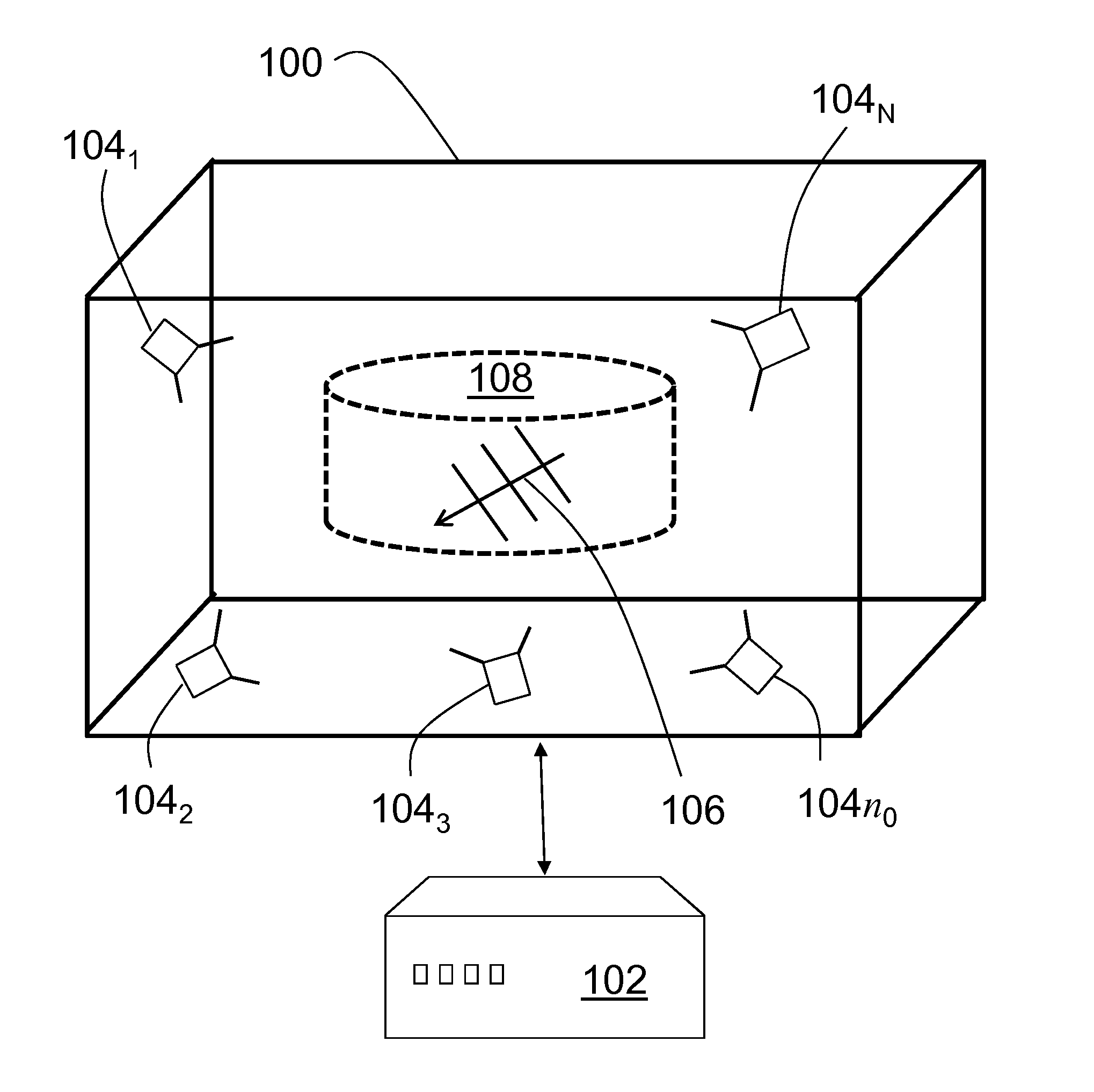
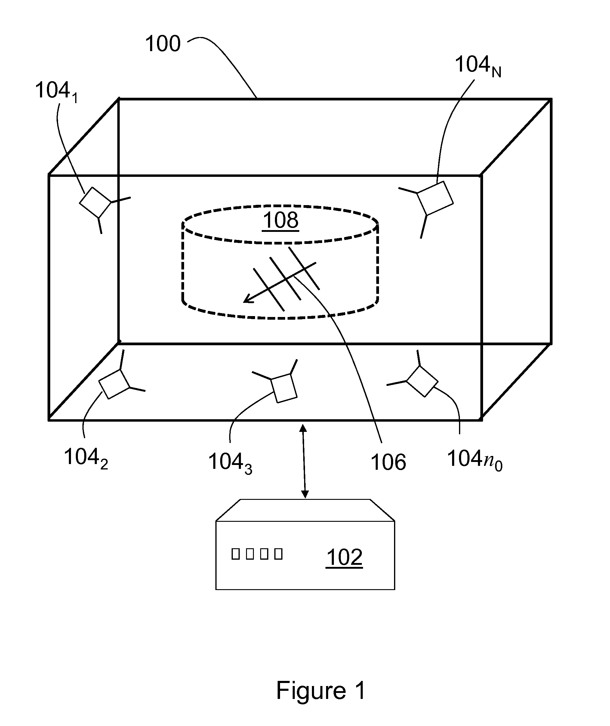
[0027]FIG. 1 illustrates a wireless test system including an anechoic chamber 100 and channel emulator 102. The anechoic chamber includes walls which are absorbing but not perfectly absorbing, so a field produced by N antennas 1041, 1042, 1043 . . . 104N disposed in the chamber is scattered by the walls. Also, a field produced by one antenna will scatter off all the other antennas. The channel emulator includes computer programs stored on non-transitory computer-readable media and processing hardware for creating, modifying, amplifying and otherwise generating signals that are provided to the antennas for transmission. In one aspect each of the antennas is fed by a time-harmonic signal with complex amplitude an, with n=1, 2, . . . , N, in order to present a single plane wave 106 in a test zone 108 in the anechoic chamber. The single plane wave may be used to test a wireless device under test (DUT) disposed in t...


PUM


Abstract

Small anechoic chambers for evaluating a wireless device under test (DUT) are characterized by a set of antennas to which a test signal is applied and for which excitation coefficients are applied such that the test signal approximates a single plane wave or a preselected superposition of plane waves in the near field of the antennas. The test-equipment antennas in the chamber may be as close as one wavelength from the boundary of a test zone in which the DUT is disposed. Hence, the test zone can be in the near field of the test-equipment antennas and the test zone can be less than a wavelength from the chamber walls. Consequently, it is possible to perform tests in a small anechoic chamber that previously required a large anechoic chamber, e.g., advanced spatial channel-model tests and antenna-pattern measurements.

Description

CROSS-REFERENCE TO RELATED APPLICATIONS[0001]Priority is claimed to U.S. Provisional Patent Application 61 / 526,300 titled Small Anechoic Chamber for Evaluation of Wireless Devices, filed Aug. 23, 2011, which is incorporated by reference in its entirety.BACKGROUND[0002]The subject matter of this disclosure relates generally to one or more of plane-wave creation, anechoic chambers, spatial channel models, and over-the-air testing of wireless devices.[0003]Anechoic chambers have been used for decades to evaluate antennas and wireless devices in a controlled environment. Channel models have been designed for use with test equipment to emulate real-world fading conditions in controlled environments. Typically the channel models are implemented in the anechoic chamber using a ring of test-equipment antennas that surround the device under test (DUT). In particular, channel emulators feed the test-equipment antennas to create the desired fading environment at the location of the DUT, which ...

Claims


Application Information

Patent Timeline
Patent Type & Authority Applications(United States)
IPC IPC(8): H04B17/00
CPCG01R29/0871G01R29/105G01R29/0892H04W24/08
Inventor HANSEN, THORKILD
Owner AZIMUTH SYSTEMS
Why Eureka
Try Eureka