Inflatable splint

Inactive Publication Date: 2013-02-28
MUSTAFA IBTESAM M Y
View PDF4 Cites 6 Cited by
  • Summary
  • Abstract
  • Description
  • Claims
  • Application Information

AI Technical Summary

Benefits of technology

[0008]The inflatable splint has several forms intended for application to different parts of the body. Each embodiment of the inflatable splint includes an inner layer or ply formed of a semi-rigid, thin shell and at least one additional pneumatically inflatable layer or ply that is secured about the rigid or semi-rigid inner shell. A second pneumatically inflatable layer or ply may be placed about the first pneumatically inflatable layer or ply, to form three layers or plies for the cast or splint assembly. The inner shell may be lined with a soft fabric liner, or alternatively a soft fabric sock or sleeve may be applied to the injured limb or other area of the body prior to installing the shell and pneumatically inflated components.
[0009]The innermost semi-rigid layer or ply comprises a pair of mutually opposed, mating portions that secure to one another about the injured limb or o

Problems solved by technology

Plaster casts are relatively heavy, and an extensive plaster cast covering the greater majority of the leg greatly reduces the mobility of the wearer of the cast due to the inability of the wearer to flex the leg and also due to the relatively high weight of the cast.
While the rigidity of the injured limb is a requirement for proper healing, the high weight of a plaster cast is a major detriment to the mobility of the wearer of the cast.
While such lightweight casts are considerably more comfortable for the wearer due to the greater ease

Method used


Image

  • Inflatable splint
  • Inflatable splint
  • Inflatable splint

Examples


first embodiment

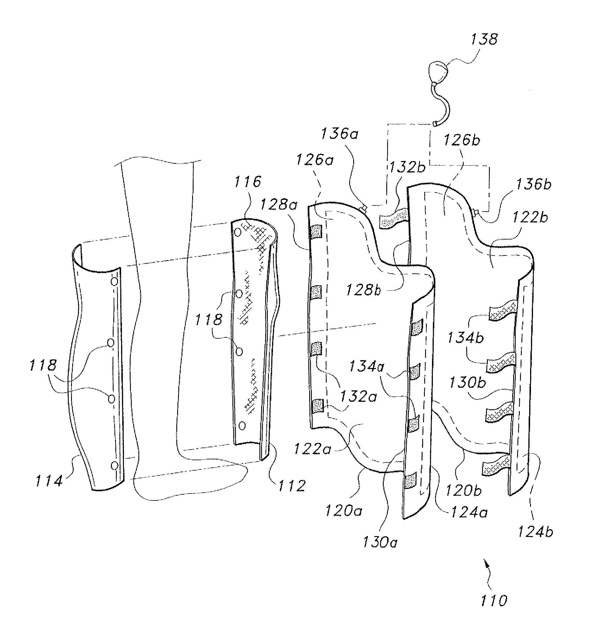
[0017]FIG. 1 of the drawings illustrates the inflatable splint. The inflatable splint 110 of FIG. 1 is configured for placement over an injured leg. The inflatable splint 110 includes a thin, semi-rigid, anatomically conforming inner shell formed of plastic, glass fiber composite, carbon fiber composite, or other suitably lightweight thin material. The shell is formed as a forward half or portion 112 and an opposite rearward half or portion 114 in the exemplary embodiment of FIG. 1. It will be seen that the shell components 112 and 114 may be formed as two lateral portions, or otherwise portioned, as desired. The shell components 112 and 114 may be configured in several sizes to fit various sizes of individuals, from smaller children to larger adults. The shell components 112 and 114 are preferably lined or covered with a soft knit or woven fabric material 116, for the comfort of the wearer. Alternatively, a conventional sock or sleeve extending the length of the shell components 11...

second embodiment

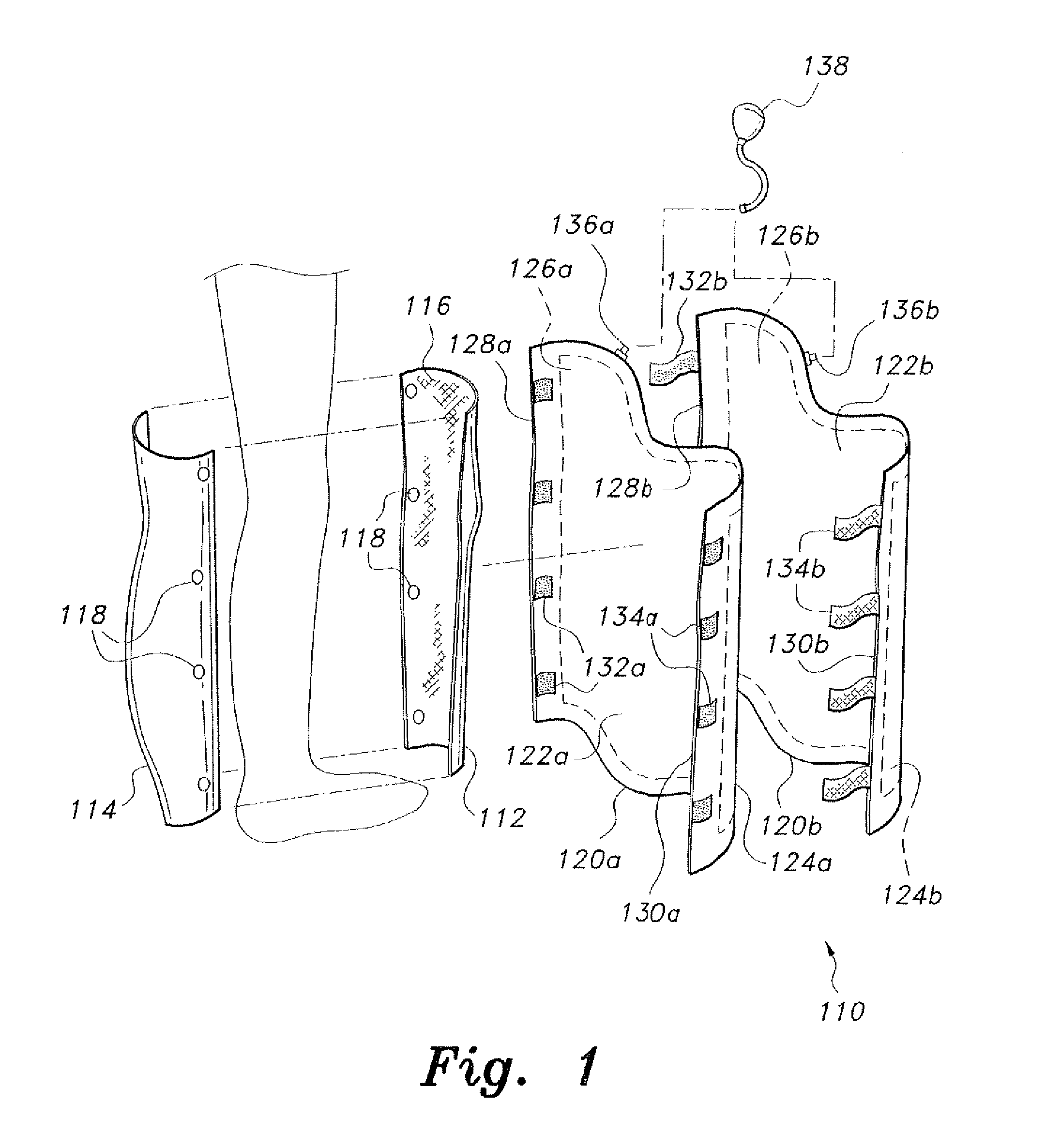
[0020]FIG. 2 of the drawings illustrates an inflatable splint comprising an inflatable splint 210 for the ankle, foot, and / or lower leg. The inflatable splint 210 of FIG. 2 is configured similar to the inflatable splint 110 of FIG. 1, having first and second semi-rigid shell portions 212 and 214 that secure about the lower leg or ankle immediately adjacent the skin. The two shell portions 212 and 214 may be formed the same materials as used for the shell portions 112 and 114 of FIG. 1, and may be formed as forward and rearward halves, lateral halves, or other portions, as desired. The shell components 212 and 214 are configured in several sizes to fit various sizes of individuals, and are preferably lined or covered with a soft knit or woven fabric material 216 for the comfort of the wearer. A sock or sleeve may be applied to the body before the shell components 212 and 214 are installed, if desired, as in the case of the inflatable splint assembly 110 of FIG. 1. The two components ...

third embodiment

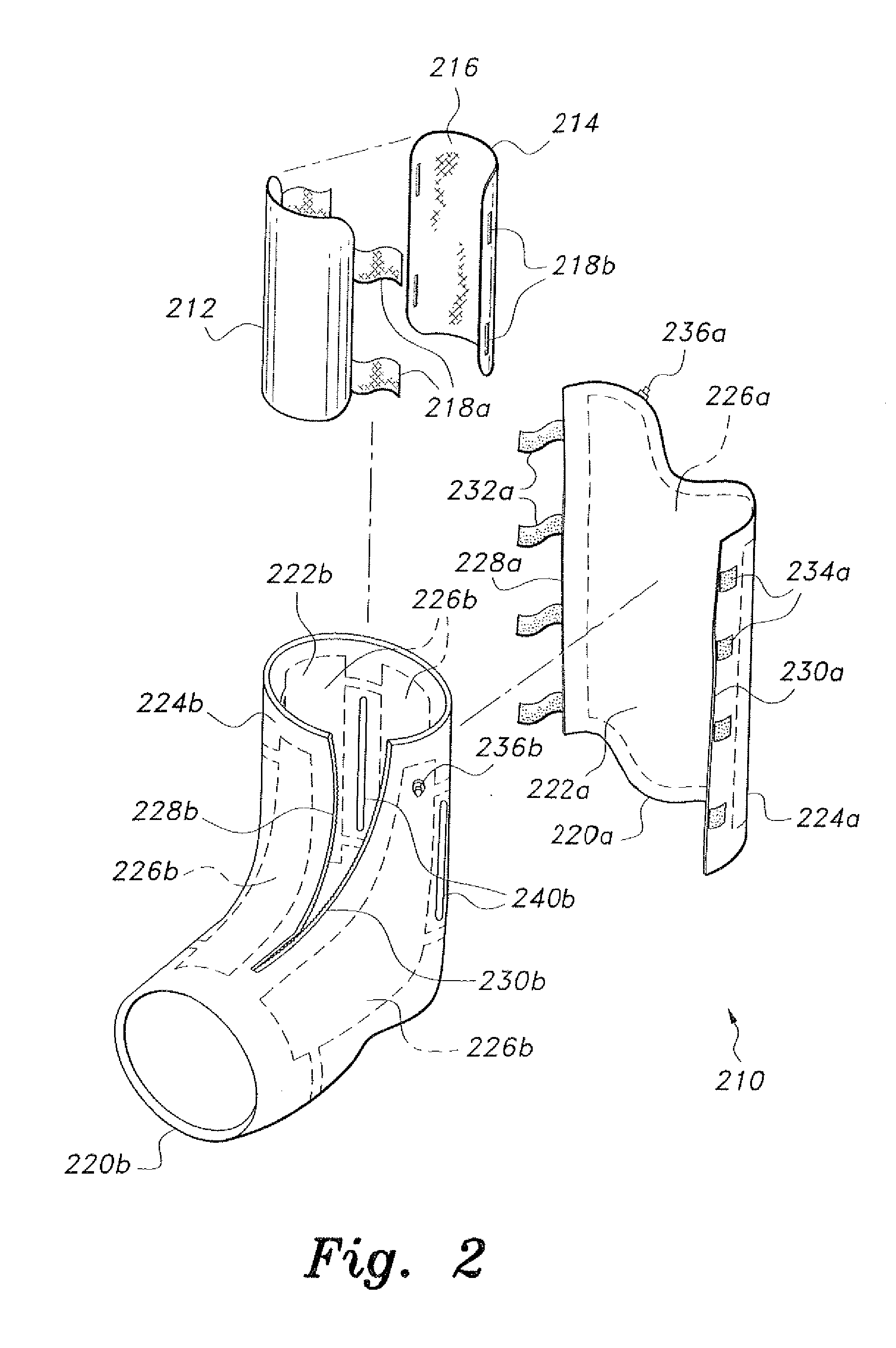
[0025]FIG. 3 of the drawings illustrates the inflatable splint, designated as inflatable splint 310. The inflatable splint 310 is configured to fit about the elbow of the wearer or patient, the device extending at least partially upward along the upper arm toward the shoulder and at least partially downward along the lower arm toward the wrist. As in the case of the other embodiments of the inflatable splint, the splint 310 includes a two-part inner shell formed of thin sheets of semi-rigid material. The two shell components 312 and 314 are preferably lined with a soft fabric liner 316, as in the case of other embodiments. The two components or portions 312 and 314 have cooperating fasteners 318a and 318b, e.g., mating hook and loop fabric material, extending from their mating peripheries. Alternative fasteners, e.g., tabs, snaps, ties, etc. may be provided.

[0026]The inflatable splint 310 of FIG. 3 includes only a single pneumatically inflated overlay 320, rather than having two suc...


PUM


Abstract

The inflatable splint is formed of an inner shell of thin, semi-rigid material and at least one pneumatically inflated ply surrounding the inner shell. A second pneumatically inflated ply may be placed around the first pneumatically inflated layer. The inner shell may be lined with a soft fabric material, or a soft fabric sock or sleeve may be applied over the injured limb for comfort. The innermost semi-rigid ply of the splint may be formed in two halves that attach removably to one another to allow the assembly to be removed from the wearer from time to time for hygiene, therapy, and/or other reasons as required. The pneumatically inflatable outer plies are each formed as a single wrap. An inflation device may be provided with the assembly, for the convenience of the wearer to adjust the inflation pressure of the outer pneumatic ply or plies.

Description

CROSS-REFERENCE TO RELATED APPLICATIONS[0001]This is a continuation of my prior application Ser. No. 13 / 219,583, filed Aug. 26, 2011 now pending.BACKGROUND OF THE INVENTION[0002]1. Field of the Invention[0003]The present invention relates to the medical field, and particularly to an inflatable splint having a semi-rigid inner ply and at least one outer ply removably attached to the inner ply, the outer ply(s) being inflatable to add rigidity and protection.[0004]2. Description of the Related Art[0005]The necessity of immobilizing a broken or badly sprained limb or torn ligament to provide for proper healing has been known for centuries. This has been conventionally accomplished by laying up a rigid plaster cast over and around the injured limb, with the plaster cast remaining in place for perhaps several weeks or perhaps a couple of months or more. Plaster casts are relatively heavy, and an extensive plaster cast covering the greater majority of the leg greatly reduces the mobility ...

Claims


Application Information

Patent Timeline
IPC IPC(8): A61F5/00
CPCA61F5/05816
Inventor MUSTAFA, IBTESAM M.Y.
Owner MUSTAFA IBTESAM M Y
Why Eureka
Try Eureka