Shim supported upon a pivot pin between upper and lower receivers of an ar-15/m16/m4 style firearm and for reducing misalignment and play

a technology of pivot pins and firearms, applied in the direction of shoulder-fired small arms, weapons, collapsible guns, etc., can solve the problems of undesirable rattling or noise, slop or play, etc., and achieve the effect of reducing or eliminating instances of slop or play

Inactive Publication Date: 2013-03-07
ELITE ARMS
View PDF1 Cites 15 Cited by
  • Summary
  • Abstract
  • Description
  • Claims
  • Application Information

AI Technical Summary

Benefits of technology

[0010]The improved shim construction incorporates a thin body exhibiting a profile generally matching a selected ear and including an arcuate perimeter with an flat interconnected base surface. The body exhibits an aperture defined therein such that, upon placement between an inner facing surface of a selected ear and the intermediate positioned cylindrical shaped portion and subsequent widthwise traversing installation of a pivot pin, the body is sandwiched between the receivers and occupies an excess tolerance, thereby reducing or eliminating instances of misaligning slop or play exhibited between the receivers.

Problems solved by technology

A problem commonly associated with such assembled receivers is the incidence of “slop” or “play” and which is defined as any degree of looseness in the tolerance established between the aligning lugs and ears.
Such looseness in the inter-fitting of the parts can be the cause of undesirable rattling or noise.

Method used


Image

  • Shim supported upon a pivot pin between upper and lower receivers of an ar-15/m16/m4 style firearm and for reducing misalignment and play
  • Shim supported upon a pivot pin between upper and lower receivers of an ar-15/m16/m4 style firearm and for reducing misalignment and play
  • Shim supported upon a pivot pin between upper and lower receivers of an ar-15/m16/m4 style firearm and for reducing misalignment and play

Examples


Embodiment Construction

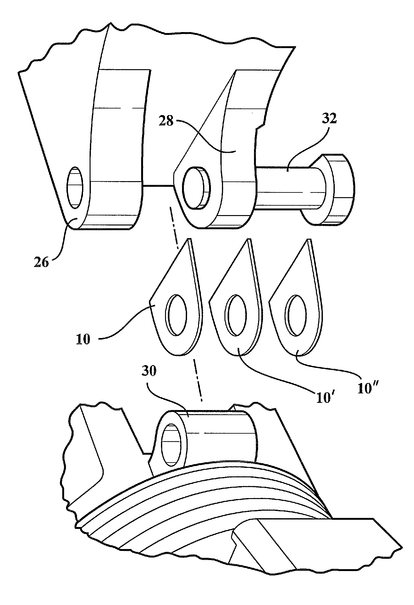
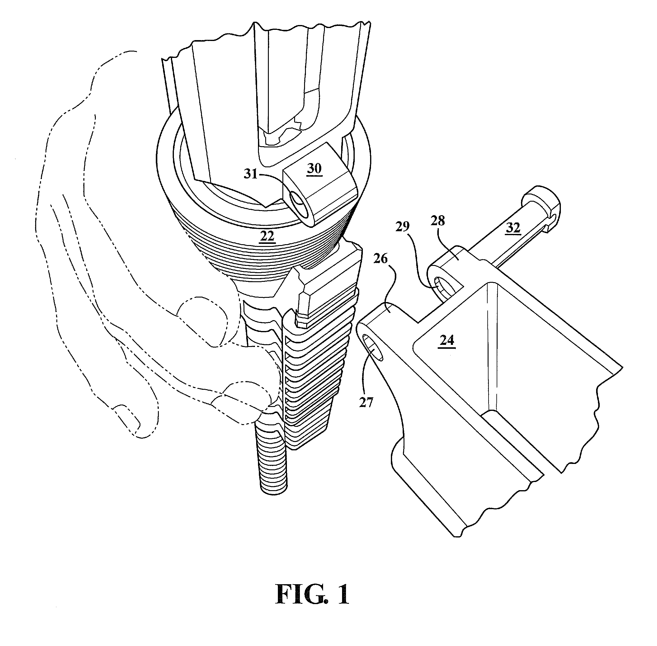
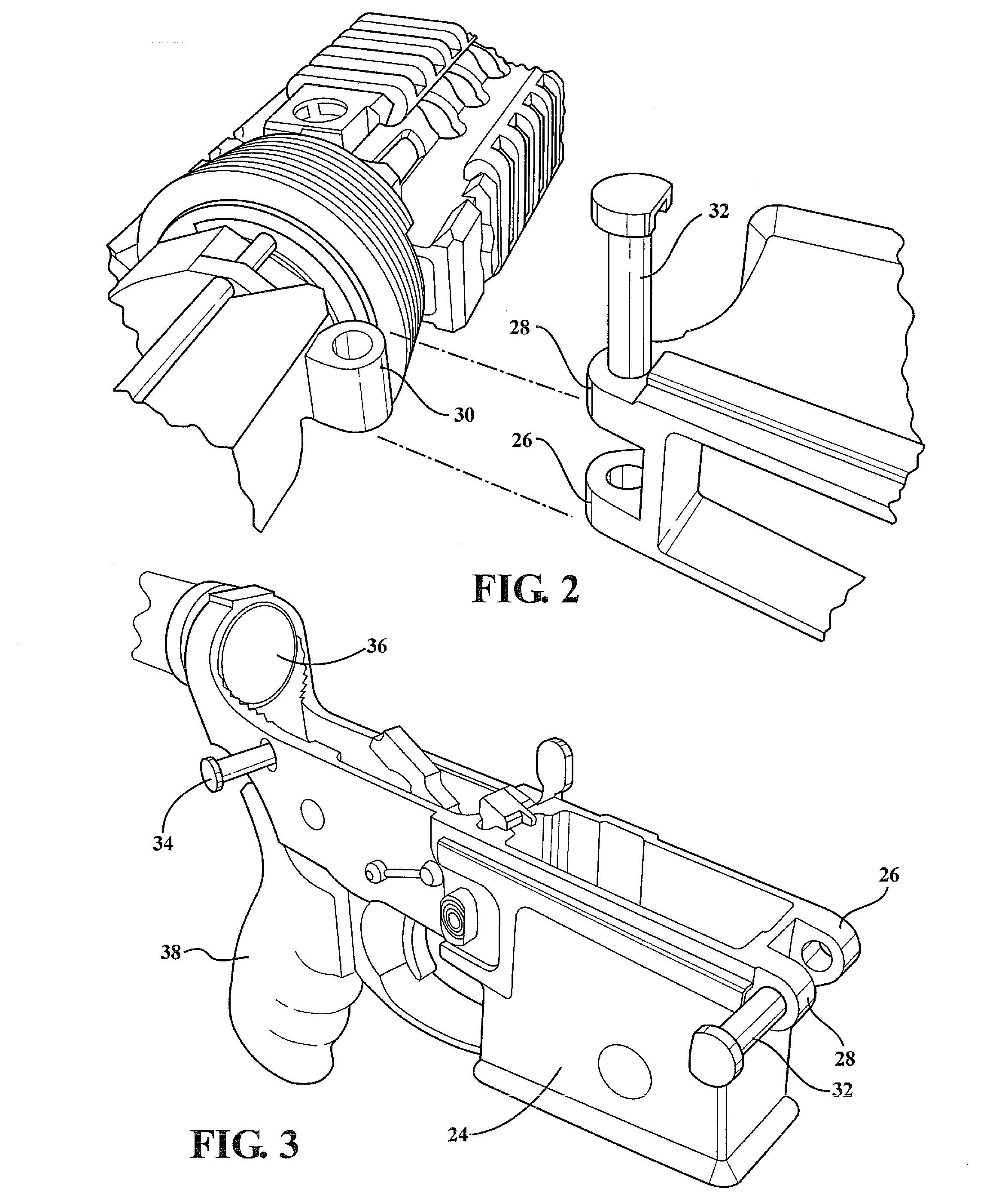
[0023]The present invention teaches an improved shim design which improves upon prior art disc shaped shims. As will be described in reference to the succeeding description, the improved shim exhibits a thin arcuate body with a flat bottom which matches an inner facing profile of either of the spaced apart ears associated with the lower receiver, and between which seats a tubular shaped and downwardly extending protrusion associated with the upper receiver. The shim can be employed either singularly or in a plural / stackable fashion and in order to eliminate the existence of excess tolerance (spacing) exhibiting between the upper and lower receives, such as which is further characterized as “slop” or “play” and which can otherwise result in misalignment between the receivers.

[0024]By controlling the slop existing between the upper and lower receivers at the front mounting location (the takedown pin defining a second rearward spaced mounting location), the firearm (rifle) can be easil...


PUM


Abstract

An improved shim construction incorporating a thin body exhibiting a profile generally matching a selected mounting ear of a lower assembleable receiver, the shim including an arcuate perimeter with an flat interconnected base surface. The body exhibits an aperture defined therein such that, upon placement between an inner facing surface of the ear and an intermediate positioned cylindrical shaped portion, a subsequent widthwise traversing installation of a pivot pin causes the shim body to be sandwiched between the receivers to occupys an excess tolerance, thereby reducing or eliminating instances of misaligning slop or play exhibited between the receivers. The shim may exhibit a thickness in a range of 0.001″ to 0.010″. A plurality of shims can be provided as a kit and which are applied in scalable fashion to compensate for varying excess tolerance established between the receivers.

Description

CROSS REFERENCE TO RELATED APPLICATIONS[0001]The present invention claims the priority of U.S. Ser. No. 61 / 530,429 filed Sep. 2, 2011.BACKGROUND OF THE INVENTION[0002]1. Field of the Invention[0003]The present invention teaches an improved shim stock design, improving upon prior art disc shaped shims. The improved shim exhibits a thin arcuate body with a flat bottom which matches the profile of either of the spaced apart ears associated with the lower receiver and between which seats a tubular shaped and downwardly extending protrusion associated with the upper receiver. The shim can be employed either singularly or in a plural / stackable fashion and in order to eliminate the existence of excess tolerance (spacing) exhibiting between the upper and lower receives, such as which is further characterized as “slop” or “play” and which can otherwise result in misalignment between the receivers.[0004]2. Background of the Relevant Art[0005]Firearms such as the M16 / M4 / AR15 rifle include uppe...

Claims


Application Information

Patent Timeline
Patent Type & Authority Applications(United States)
IPC IPC(8): F41A3/66
CPCF41A11/04
Inventor WATKINS, SCOTT ERIC
Owner ELITE ARMS
Why Eureka
Try Eureka