LED unit
a technology of led units and led parts, applied in the direction of basic electric elements, printing, other printing apparatuses, etc., can solve the problems of reducing luminous efficiency, complicated configuration, increasing the number of components, etc., and achieve the effect of reducing the cost of ink
- Summary
- Abstract
- Description
- Claims
- Application Information
AI Technical Summary
Benefits of technology
Problems solved by technology
Method used
Image

Examples
first embodiment
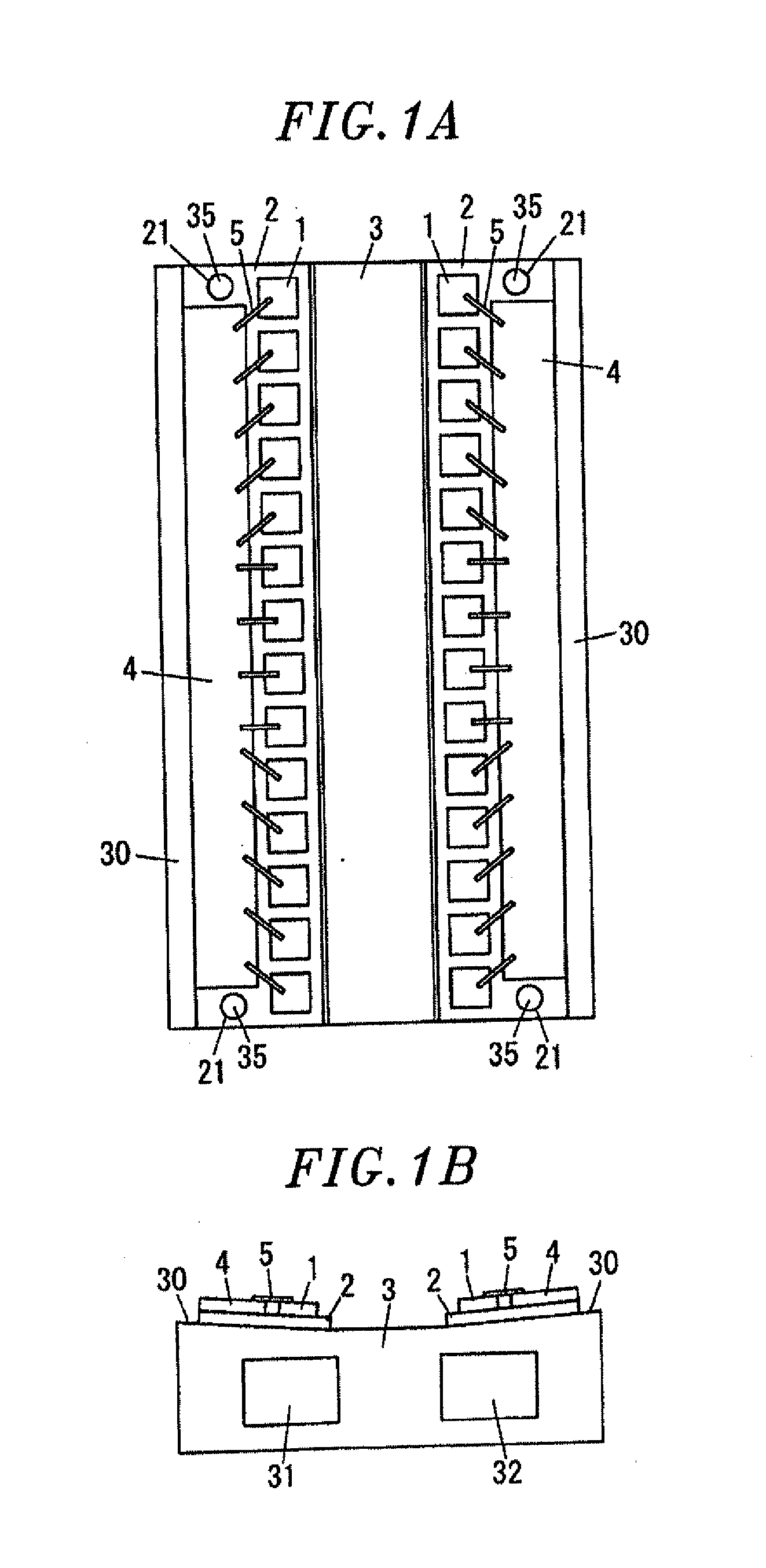
[0044]An ultraviolet ray irradiation unit that irradiates ultraviolet rays to harden ink printed on a target object is installed at a rear end of a printing unit for performing printing on the target object by using ink that can be hardened by irradiation of ultraviolet rays. An LED unit of the present embodiment is used in the ultraviolet ray irradiation unit and has a configuration in which two base blocks 2, each having a plurality of LED modules 1 mounted thereon, are arranged on a heat radiation member 3, as shown in FIGS. 1A and 1B.
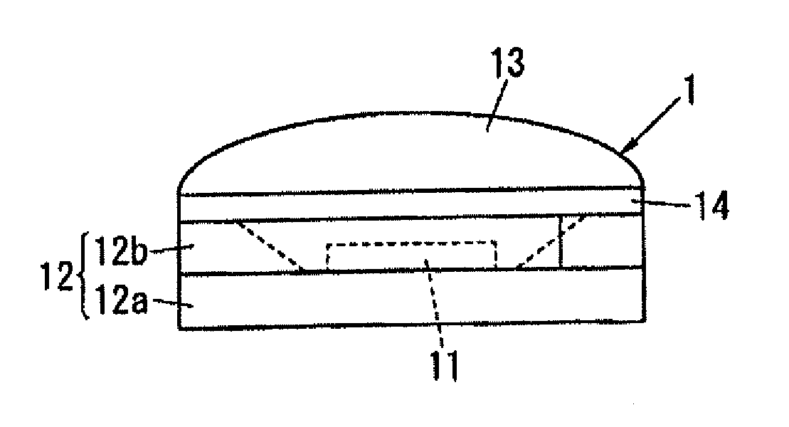
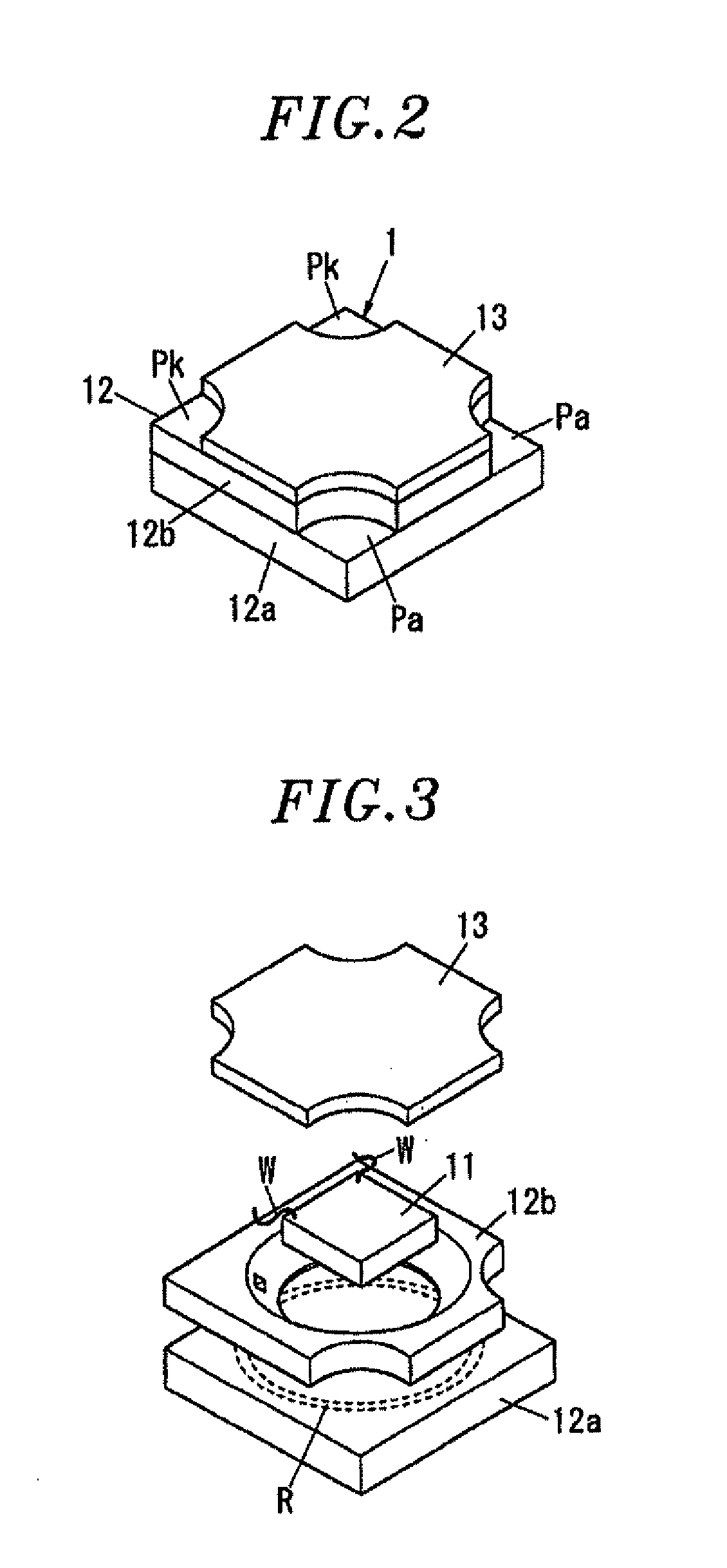
[0045]As shown in FIGS. 2 and 3, each of the LED modules 1 includes an LED chip 11, a package 12 accommodating therein the LED chip 11, and a lens 13 covering an opening in the package 12. The package 12 includes a sub-mount substrate 12a having a top surface to which the LED chip 11 is AuSn-bonded, and a frame 12b that is AuSn-bonded to the top surface of the sub-mount substrate 12a so as to surround the LED chip 11.
[0046]The sub-mount substrate 12...
second embodiment
[0072]As shown in FIGS. 5A and 5B, the LED unit of the present embodiment is configured by providing four base blocks 2, on each of which a plurality of LED modules 1 is mounted, on the heat radiation member 3.
[0073]Therefore, the ultraviolet rays are irradiated in a wide range in a width direction of a target object, and the irradiation range in a lengthwise direction of the object is also expanded.
[0074]The heat radiation member 3 of the present embodiment is formed of a rectangular copper plate and serves as a supporting base having on one surface thereof two inclined surfaces 30a and 30b where the base blocks 2 on each of which the LED modules 1 are mounted are arranged in four rows along a lengthwise direction.
[0075]The inclined surfaces 30a have a rectangular shape elongated along the lengthwise direction of the heat radiation member 3 and are formed at the central portion in the width direction of the heat radiation member 3. Thus, the two inclined surfaces 30a are inclined i...
third embodiment
[0090]As shown in FIGS. 6A and 6E, in the LED unit of the present embodiment, the heat radiation member 3 of the second embodiment is divided into multiple portions in a width direction thereof, and a base block is disposed at an inclined surface of each divided portion of the heat radiation member.
[0091]In this embodiment, the heat radiation member 3 includes a rectangular heat radiation member 3A and rectangular heat radiation members 3B and 3C attached to both sides in the width direction of the heat radiation member 3A.
[0092]In the heat radiation member 3A, two inclined surfaces 30a inclined in opposite directions are formed at both sides in the width direction of the heat radiation member 3A, so that the base block 2 on which the LED modules 1 are mounted is disposed on each inclined surface 30a.
[0093]The heat radiation members 3B and 3C are attached to the long lateral sides of the heat radiation member 3A. The inclined surfaces 30b formed at the heat radiation members 3B and...
PUM
 Abstract
Description
Claims
Application Information
 - R&D
- Intellectual Property
- Life Sciences
- Materials
- Tech Scout
- Unparalleled Data Quality
- Higher Quality Content
- 60% Fewer Hallucinations
Browse by: Latest US Patents, China's latest patents, Technical Efficacy Thesaurus, Application Domain, Technology Topic, Popular Technical Reports.
© 2025 PatSnap. All rights reserved.Legal|Privacy policy|Modern Slavery Act Transparency Statement|Sitemap|About US| Contact US: help@patsnap.com