
Jacket structure for offshore constructions

a construction and offshore technology, applied in the direction of rod connections, manufacturing tools, branching pipes, etc., can solve the problems of relatively complex welded joints, comparatively complex connection methods, etc., and achieve the effect of good stability of inventive bolted connections and increased bolted joints

Inactive Publication Date: 2013-03-07
SIEMENS AG
View PDF23 Cites 5 Cited by
  • Summary
  • Abstract
  • Description
  • Claims
  • Application Information

AI Technical Summary

Benefits of technology

The present invention proposes a jacket structure that uses bolted joints instead of welded joints for connecting node members with the jacket structure. This provides a mechanically stable and cost-effective way of installing the jacket structure on a site. The bolted connections are easy to maintain and the jacket structure allows for flexibility in parameters like diameters, wall thicknesses, angles, etc. The invention also includes a ready-to-connect node arrangement and an adapter profile for easily connecting the node member with the jacket structure. The bolted connection between the node member and the adapter profile ensures a fast and firm connection. The technical effects of the invention include improved stability, flexibility, and ease of installation and maintenance.

Problems solved by technology

Yet, welding represents a comparatively complex connecting method for establishing a stable connection of the node members with respective parts of the jacket structure, that is foremost the profiles of the jacket structure.
Altogether, welded joints are fairly complex in planning and realisation.

Method used


Image

  • Jacket structure for offshore constructions
  • Jacket structure for offshore constructions
  • Jacket structure for offshore constructions

Examples


third embodiment

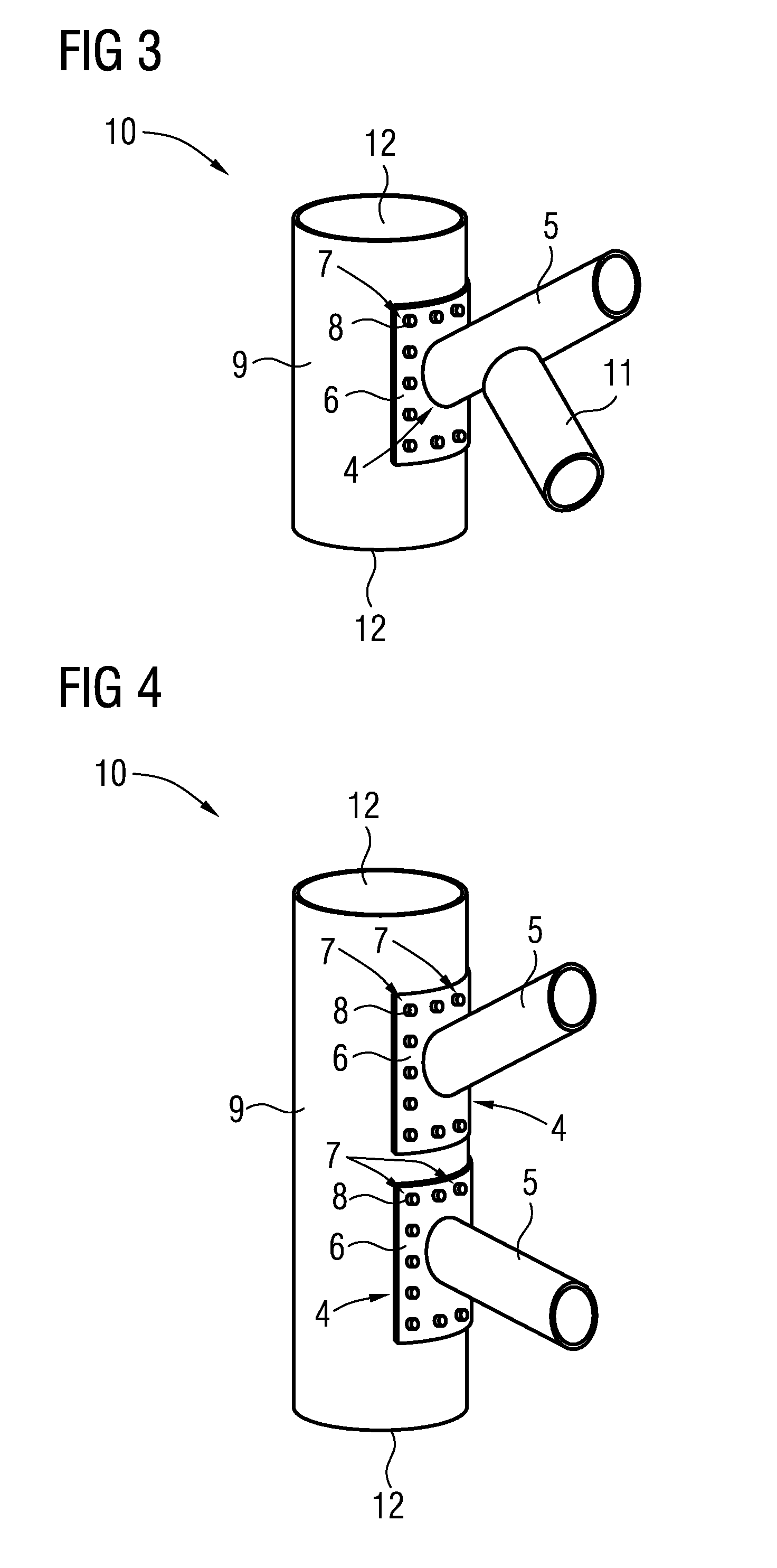
[0038]FIG. 4 shows an inventive node arrangement 10, which is characterized in that the adapter profile 9 is connected with two separate node members 4 as they are depicted in FIG. 1.

[0039]In such a manner, the node arrangement 10 may also be connected with two separate second profiles 3 of the inventive jacket structure 1, whereby in the embodiment according to FIG. 4 each node member 4 may be separately connected with a respective second profile 3 (not shown) by means of the respective connecting members 5.

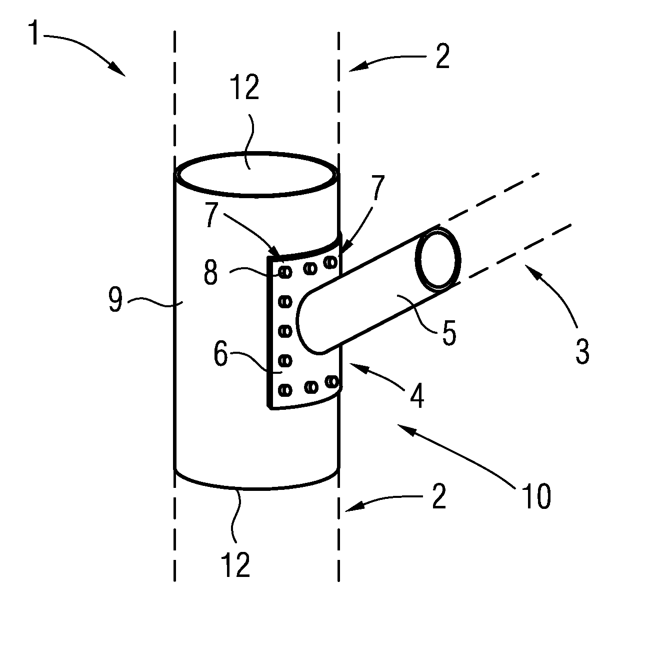
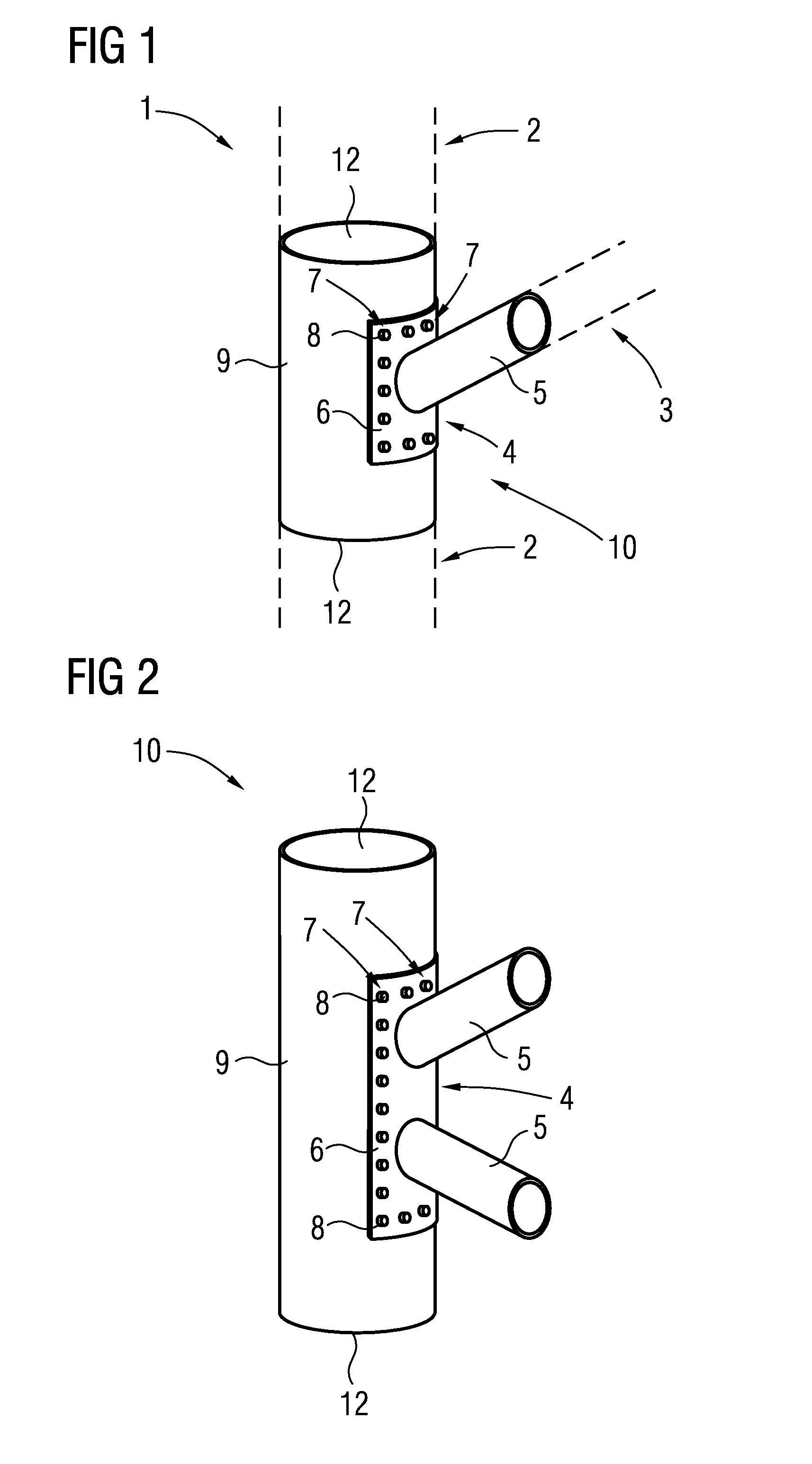
[0040]All node arrangements 10, that is the ones depicted in FIGS. 1 to 4 comprise axial connecting portions 12 disposed at the free axial endings of the adapter profile 9, so that the adapter profile 9 and the node arrangement 10 as a whole may be connected to adjacently disposed first profiles 2 of the jacket structure 1 (not shown) by means of welded or bolted joints for instance.

second embodiment

[0041]FIG. 5 shows a jacket structure 1 according to the invention. In this case, the node member 4 is directly joint to a first profile 2 of the jacket structure 1 by means of a bolted connection, that is bolts 8 penetrate through the bores 7 of the base plate 6 of the node member 4 into corresponding openings within the first profile 2. Hence, the embodiment according to FIG. 5 represents a basic principle of the present invention, whereby a bolted connection provides a detachable, yet mechanically stable connection of a node member 4 with the jacket structure 1, that is a first profile 2 of the jacket structure 1.


PUM


Abstract

Jacket structure for offshore constructions, particularly jacket structure for offshore wind turbines, including a number of first and second profiles, whereby the first profiles include rods in axial alignment and the second profiles include rods in an angled alignment relative to the first profiles, and a number of node members providing a connection site for the second profiles, wherein the node members are connected to the first profiles and / or at least one adapter profile connected to at least one first profile of the jacket structure via a bolted connection.

Description

CROSS REFERENCE TO RELATED APPLICATIONS[0001]This application is the US National Stage of International Application No. PCT / EP2010 / 063546, filed Sep. 15, 2010 and claims the benefit thereof. The International Application claims the benefits of European application No. 10163754.4 filed May 25, 2010. All of the applications are incorporated by reference herein in their entirety.FIELD OF INVENTION[0002]The invention relates to a jacket structure for offshore constructions, particularly a jacket structure for offshore wind turbines, comprising a number of profiles in axial or angled alignment and a number of node members.BACKGROUND OF INVENTION[0003]Offshore constructions for structures to be installed in the sea are usually necessary in particular for offshore wind power plants, that is offshore wind turbines and represent a constructive challenge as the respective structure has to be erected on the seabed by means of an appropriate foundation.[0004]A number of different types of found...

Claims


Application Information

Patent Timeline
IPC IPC(8): F16B7/00
CPCE02D27/42Y10T403/46Y02E10/728E04H12/10E02B17/0004E02D27/425Y02E10/727
Inventor STIESDAL, HENRIK
Owner SIEMENS AG
Learn More