Laval nozzle

Active Publication Date: 2013-03-07
ROBERT BOSCH GMBH
View PDF6 Cites 6 Cited by
  • Summary
  • Abstract
  • Description
  • Claims
  • Application Information

AI Technical Summary

Benefits of technology

[0014]The advantage associated with the nozzle arrangement according to the invention is apart from the previously mentioned advantages of the Laval nozzle according to the invention essentially that the flow cross-sections of the Laval nozzle can be synchronously actuated or adjust

Problems solved by technology

This is not

Method used


Image

  • Laval nozzle
  • Laval nozzle
  • Laval nozzle

Examples


Embodiment Construction

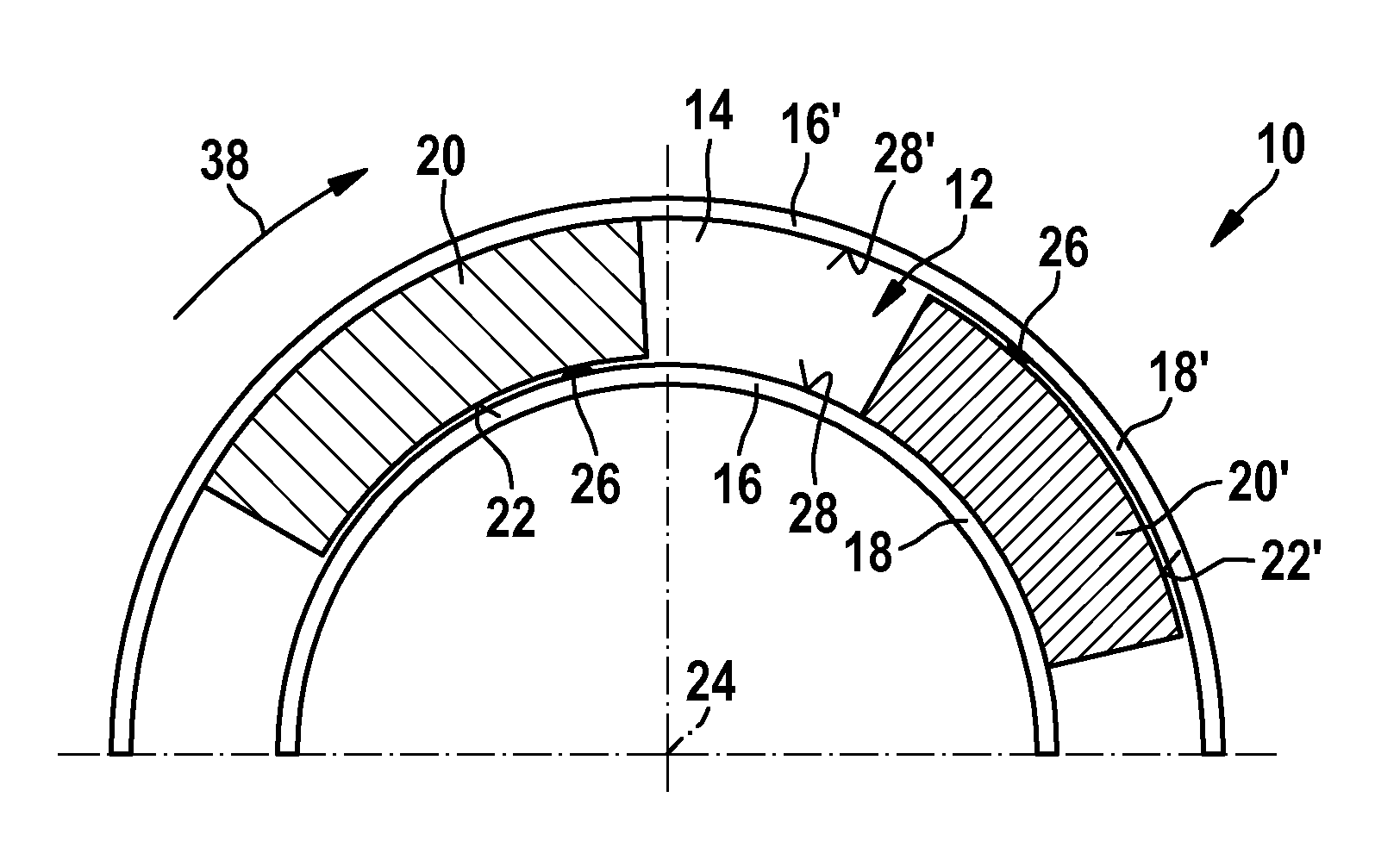
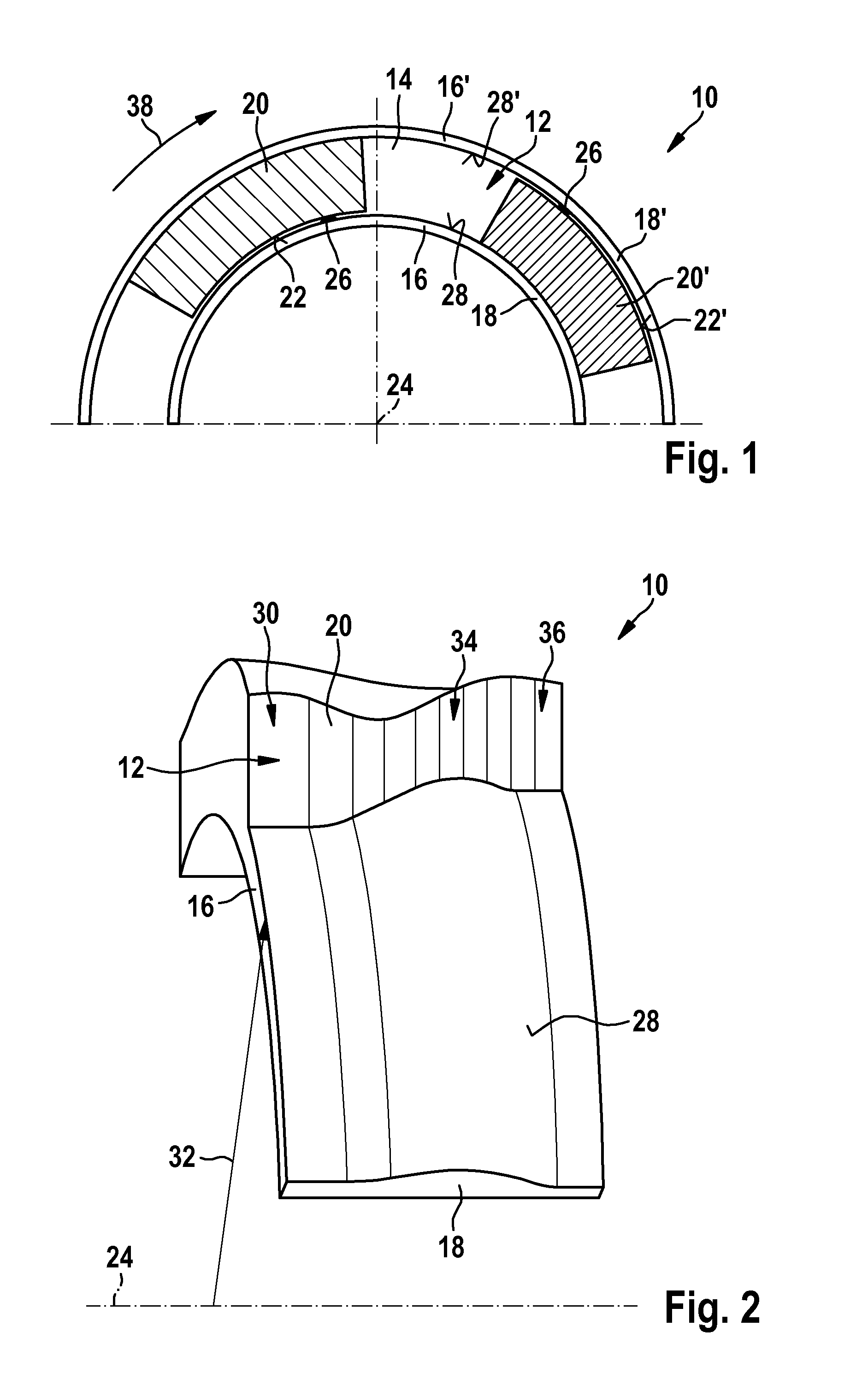
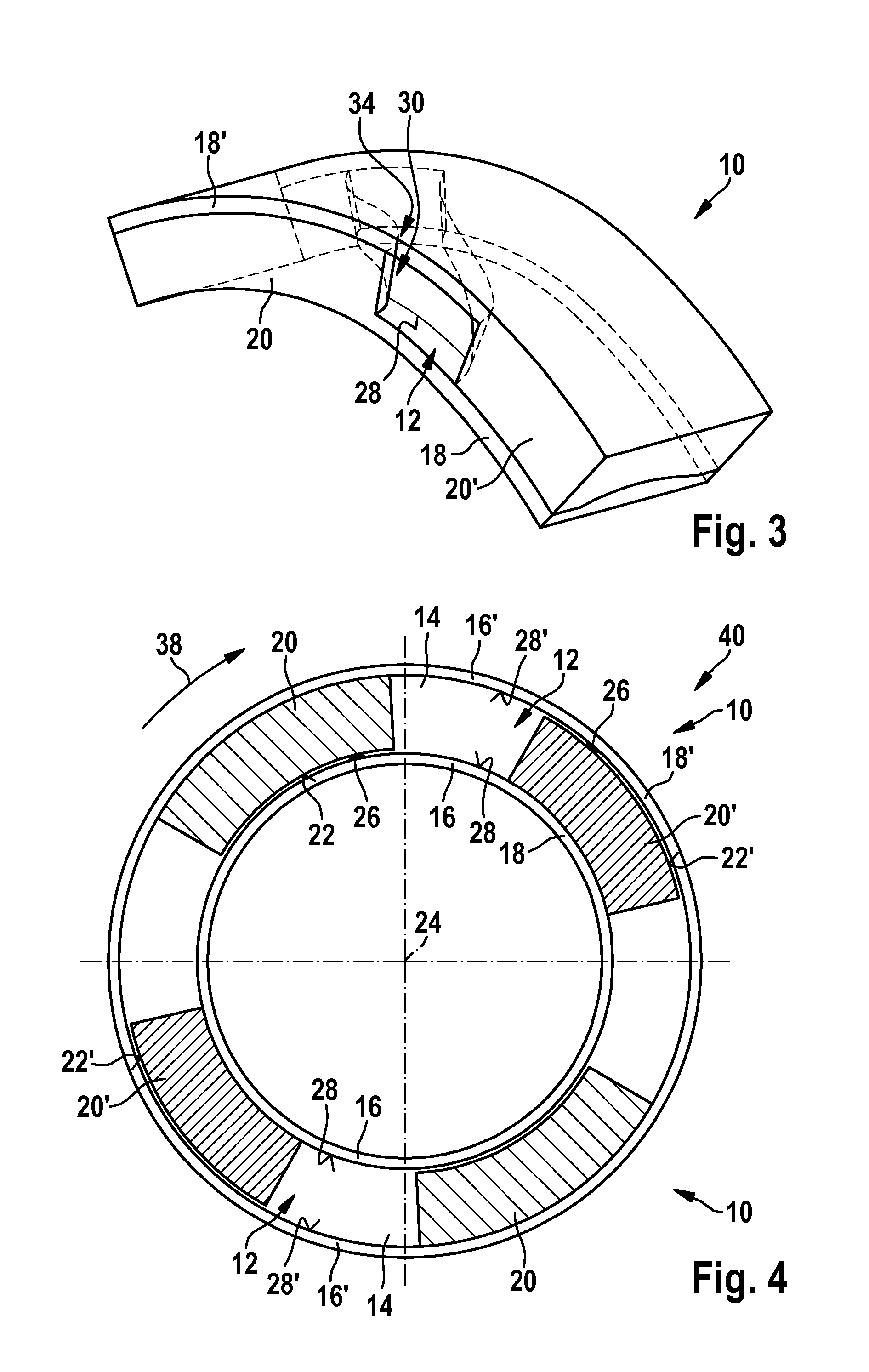
[0025]In FIG. 1, a Laval nozzle denoted entirely with the reference numeral 10 is depicted in a sharply schematized manner, which comprises a flow channel 12 having a substantially rectangular flow cross-section 14, which has an overall convergent-divergent profile along the flow channel 12.

[0026]The flow channel 12 has mutually opposing first flow channel walls 16, 16′, which are formed by two nozzle bodies 18, 18′ spaced a fixed distance apart from one another, said nozzle bodies being disposed coaxially and one inside the other.

[0027]The flow channel 12 is delimited in the circumferential direction of the nozzle bodies 18, 18′ by two mutually opposite second flow channel walls 20, 20′, which in each case are disposed between the two nozzle bodies 18, 18′.

[0028]The second flow channel walls 20, 20′ are in each case formed from one of the two nozzle bodies 18, 18′ and dimensioned in such a way that said flow channel walls fit closely to the respective other nozzle body 18, 18′ with...


PUM


Abstract

In a Laval nozzle (10) having a flow channel (12), which has a flow cross-section (14) extending in a convergent-divergent manner, according to the invention the flow channel (12) comprises mutually opposing first flow channel walls (16, 16′), which are formed by two nozzle bodies (18, 18′) spaced a fixed distance apart from one another. Two mutually opposite second flow channel walls (20, 20′), which can be moved relative toward one another or away from one another for adjusting the flow cross-section (14) of the flow channel (12), are disposed between the nozzle bodies (18, 18′).

Description

BACKGROUND OF THE INVENTION[0001]The invention relates to a Laval nozzle having a flow channel, which has a flow cross-sectional profile extending in a convergent-divergent manner.[0002]Laval nozzles of this kind are, for example, used for the purpose of transferring the enthalpy of a working fluid flowing through the Laval nozzle into kinetic energy, i.e. to accelerate the flowing working fluid to as high a speed as possible. The working fluid delivered to the Laval nozzle with subsonic speed is thereby initially accelerated by means of the convergent flow cross-section in the nozzle inlet of the Laval nozzle and thereby achieves the specific sonic speed thereof in the region of the critical, i.e. the smallest, flow cross-section of the flow channel in order to be accelerated further to supersonic speed in the region of a nozzle outlet disposed downstream, which has a divergent flow cross-section. The kinetic energy of the working fluid accelerated in such a way can subsequently, f...

Claims


Application Information

Patent Timeline
IPC IPC(8): F01D9/02F01D1/04B05B1/00
CPCF01D1/04F01D9/02F05D2240/128F02C7/042F01D17/148
Inventor HASEMANN, HEINRICHSCHMITT, MANFREDKRINN, ILONABANZHAF, BERNDSTEGMAIER, JUERGENGLASER, PATRICK
Owner ROBERT BOSCH GMBH
Why Eureka
Try Eureka