
Printing composition and a printing method using the same

a printing composition and composition technology, applied in printing, inks, polyether coatings, etc., can solve the problems of increasing process costs, increasing environmental pollution, and requiring a lot of time and many costs, and achieve the effect of improving drying problems and forming patterns of fine line width

Inactive Publication Date: 2013-03-07
LG CHEM LTD
View PDF16 Cites 4 Cited by
  • Summary
  • Abstract
  • Description
  • Claims
  • Application Information

AI Technical Summary

Benefits of technology

The present invention relates to a printing composition that improves the drying and absorption problems when a solvent evaporates into the air and when an ink absorbs into a blanket, making it useful for creating fine line patterns.

Problems solved by technology

The indirect pattern forming method does not use a photoresist material and a stripping solution in addition to a film on which a pattern will be formed, thereby increasing a process cost due to a cost of the photoresist material and the stripping solution and a cost of removing the photoresist material and the stripping solution.
In addition, there is a problem in that an environment is polluted by removing the above materials.
In addition, since the indirect method has the large number of processes and is complicated, much time and many costs are required, and in the case where the photoresist material is not sufficiently stripped, there is a problem in that defects occur in the final products.
In detail, in the case of directly printing the pattern of the fine line width, since a line height and a line width become small as compared to the case where the pattern having a thick line width is printed, the solvent is volatilized into the air or is absorbed into a silicon blanket during the printing process, thus maximizing a problem of drying the printing composition.
In the case where the drying of the solvent into the air is too fast, as the ink composition is dried on cliché in doctoring, a residual film is generated, such that in pattern transferring, for example, in an off, a problem of printing non-uniformity occurs.
Meanwhile, if the absorption of the solvent into the silicon blanket is too much, poor transferring into the substrate may occur in setting because of the drying of the printing composition on the surface of the blanket.

Method used


Image

  • Printing composition and a printing method using the same
  • Printing composition and a printing method using the same
  • Printing composition and a printing method using the same

Examples


example 1

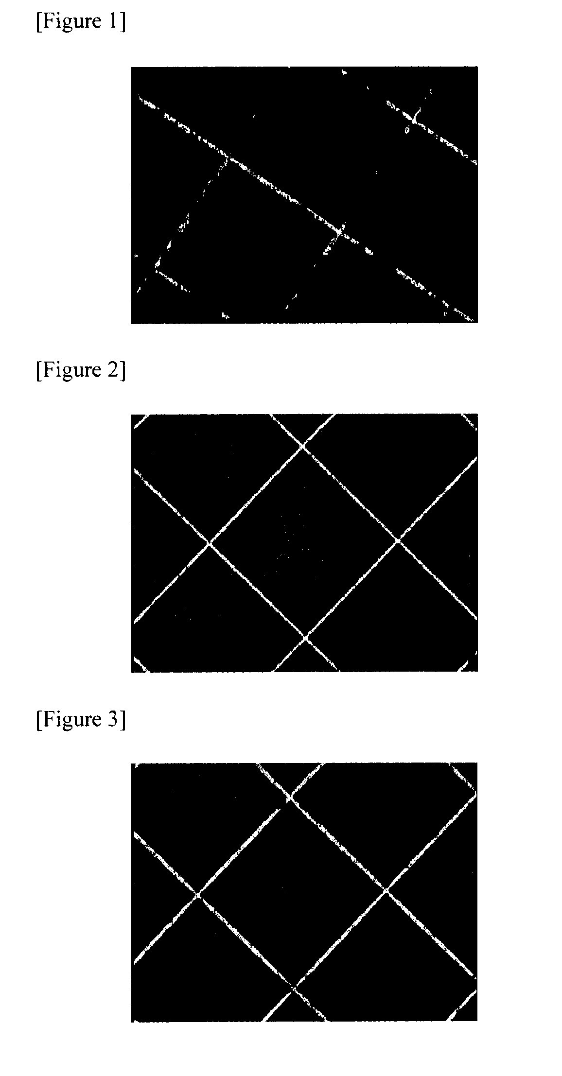
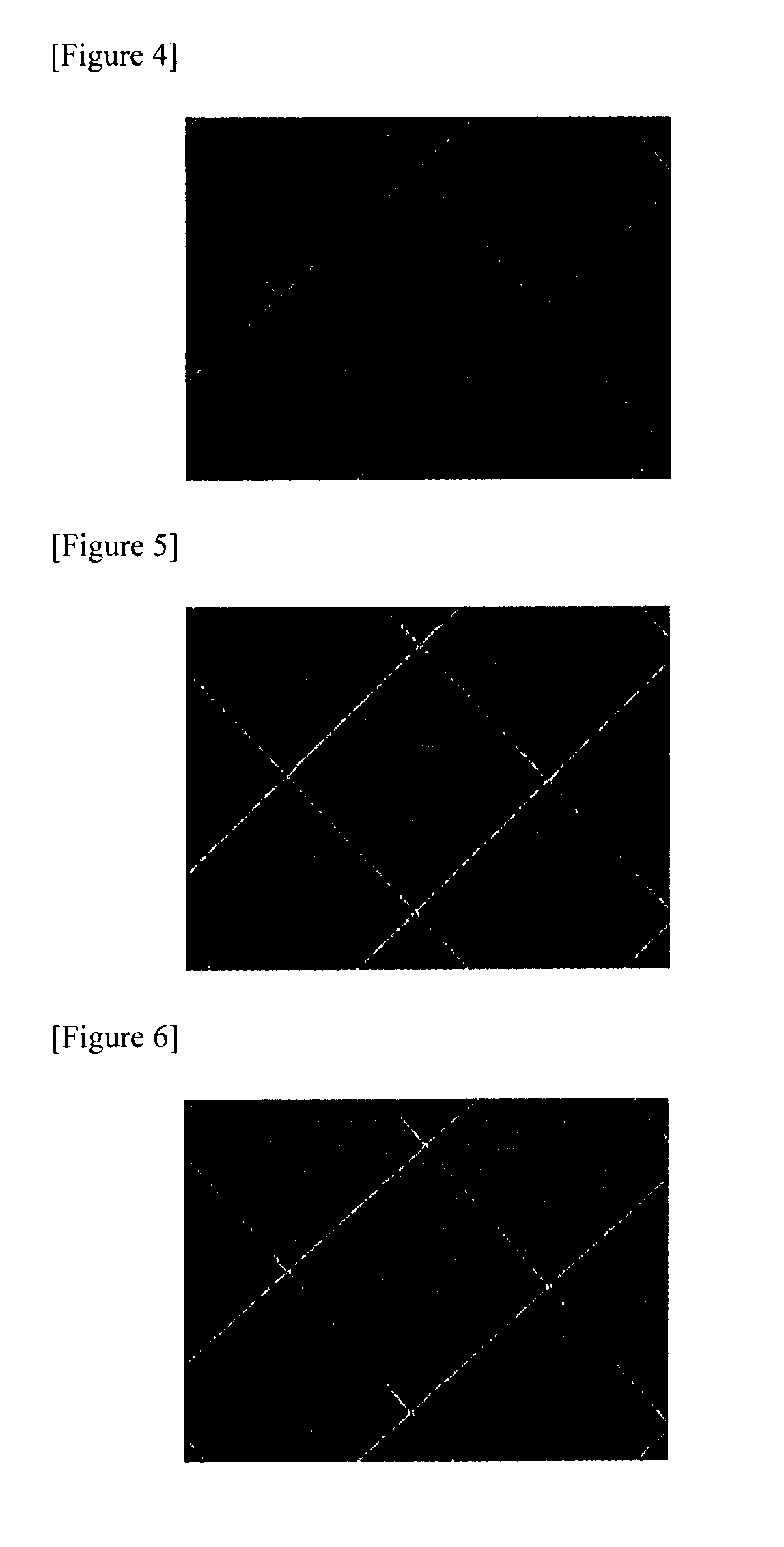
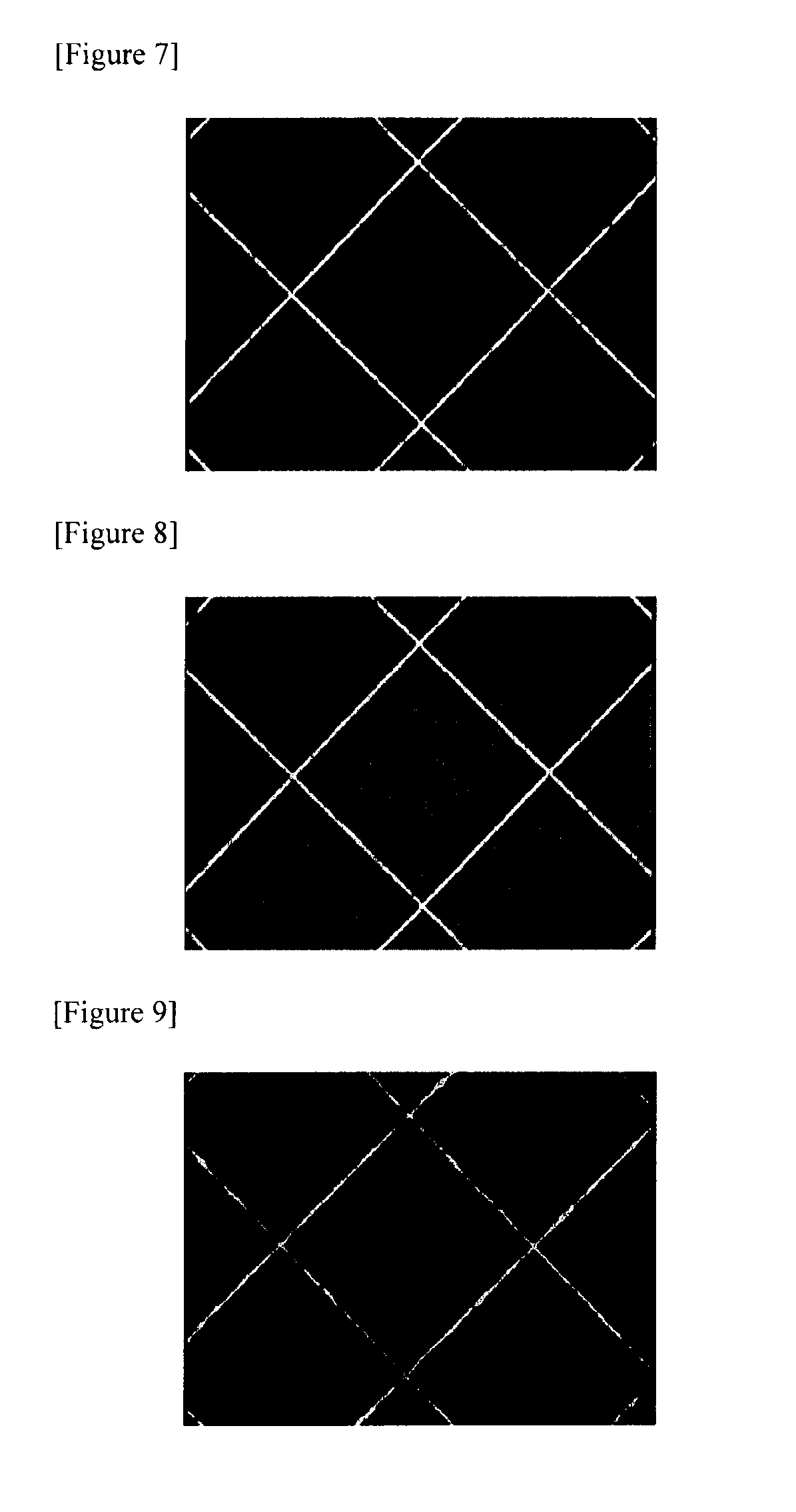
[0052]The printing composition (viscosity of 6000 cps) including the nanosilver paste (nanosilver 20 nm 70%, solvent 30%; the solvent is a mixture of alpha-terpineol and BCA (mixture of butyl carbitol acetate) and 5 wt % of 1-butyl-1-methyl pyrrolidinium bis(trifluoromethyl sulfonyl)imide on the total weight thereof was printed in the gravure offset manner at the relative humidity of 44%. In this case, the time from off to setting (hereinafter, referred to as a waiting time; Off is that all pastes on the cliché are transferred onto the silicon blanket, and Setting is that the paste on the blanket is transferred onto the substrate. Accordingly, the time after off is finished and directly before Setting starts is the waiting time was 0 sec. The printing result was shown in FIG. 2.

example 2

[0053]The same process as Example 1 was performed, except that the waiting time was 30 sec. The printing result was shown in FIG. 3. Even though the waiting time was 30 sec, it could be confirmed that the printing state was good.

example 3

[0054]The printing was performed in the same manner as Example 1, except that the waiting time was fixed to 0 sec and the composition of the ionic liquid was changed to 0.1, 0.5, and 1.5%. The printing results were shown in FIGS. 4 to 7. It could be confirmed that the printing state was good in the range of the composition.


PUM

PropertyMeasurementUnit
melting pointaaaaaaaaaa
boiling pointaaaaaaaaaa
heightaaaaaaaaaa

Abstract

The present invention relates to a printing composition including an ionic liquid, a printing method using the same, and a pattern formed by using the same. The printing composition according to the exemplary embodiment of the present invention is useful in providing a pattern of a fine line width.

Description

DISCLOSURE[0001]1. Technical Field[0002]The present invention relates to a printing composition and a printing method using the same. More particularly, the present invention relates to a printing composition that can implement a fine line width and a printing method using the same. This application claims priority from Korean Patent Application No. 10-2010-0078973 filed on Aug. 16, 2010 in the KIPO, the disclosure of which is incorporated herein by reference in its entirety.[0003]2. Background Art[0004]As a method for forming a pattern, there are an indirect pattern forming method such as a photolithography method and a direct pattern forming method such as a method in which a pattern is directly printed on a target substrate.[0005]The indirect pattern forming method may be performed by the following process. First, a photoresist pattern is formed by uniformly coating photoresist on a film formed on a substrate and selectively exposing and developing the photoresist. Subsequently, ...

Claims


Application Information

Patent Timeline
Patent Type & Authority Applications(United States)
IPC IPC(8): C09D5/00C07D207/06H01B1/12C09D133/08C09D141/00C09D163/00C09D175/04C09D167/00C09D171/00C09D171/10C09D183/00C09D179/08B41M1/00B32B3/10C07D233/58
CPCC09D11/03C09D11/38Y10T428/24802Y10T428/24893B41M5/0023C09D11/033B41M1/00C09D5/00
Inventor CHUN, SANG KIHWANG, IN-SEOKLEE, DONG WOOKSON, YONG KOO
Owner LG CHEM LTD
Learn More