Pressure controlling system and pressure controlling method

Inactive Publication Date: 2013-03-14
HONG FU JIN PRECISION IND (SHENZHEN) CO LTD +1
View PDF6 Cites 4 Cited by
  • Summary
  • Abstract
  • Description
  • Claims
  • Application Information

AI Technical Summary

Benefits of technology

The present patent is about a pressure controlling system and method that can efficiently control the pressure of a gas transmitting device. The system includes a power supply cabinet, a power controlling module, a pressurized cabinet, and a pressurized device connected to the pressurized cabinet. The power controlling module sets parameters for the gas transmitting device, and the pressurized cabinet increases the pressure of the gas transmitting device from a first pressure value to a second pressure value using a pressurized valve. The system also includes a filtrating valve to filter out impurities and a pressure adjusting valve to adjust the second pressure value. The technical effect of this patent is to provide a more efficient and effective method for controlling the pressure of a gas transmitting device.

Problems solved by technology

However, the gate often has a large size and a lot of time may be required to remove and trim the gate off the part.
Thus, removal of the gate may cause the injection molding process to be less efficient.

Method used


Image

  • Pressure controlling system and pressure controlling method
  • Pressure controlling system and pressure controlling method
  • Pressure controlling system and pressure controlling method

Examples


Embodiment Construction

[0012]The disclosure is illustrated by way of example and not by way of limitation in the figures of the accompanying drawings in which like references indicate similar elements. It should be noted that references to “an” or “one” embodiment in this disclosure are not necessarily to the same embodiment, and such references mean at least one.

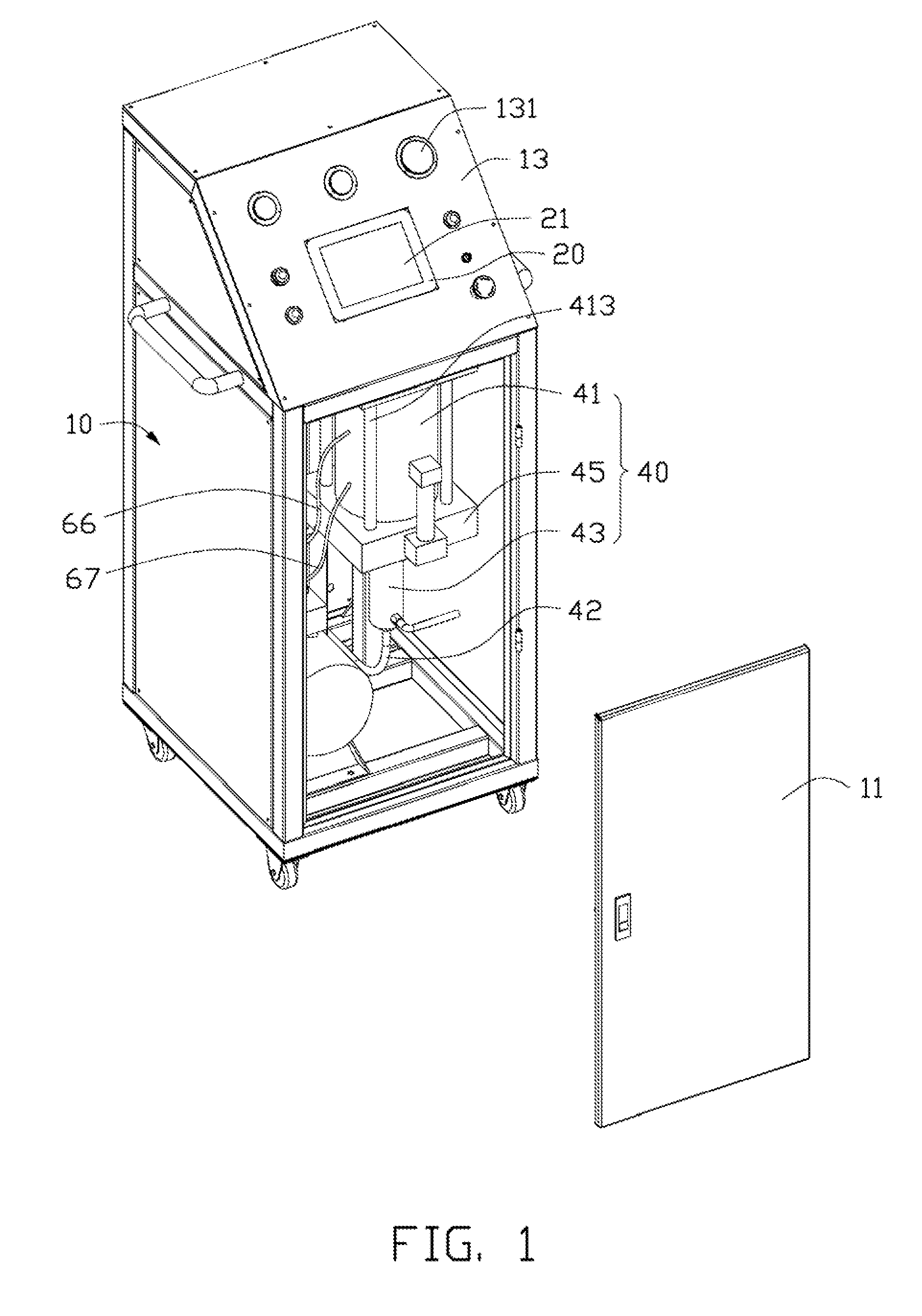
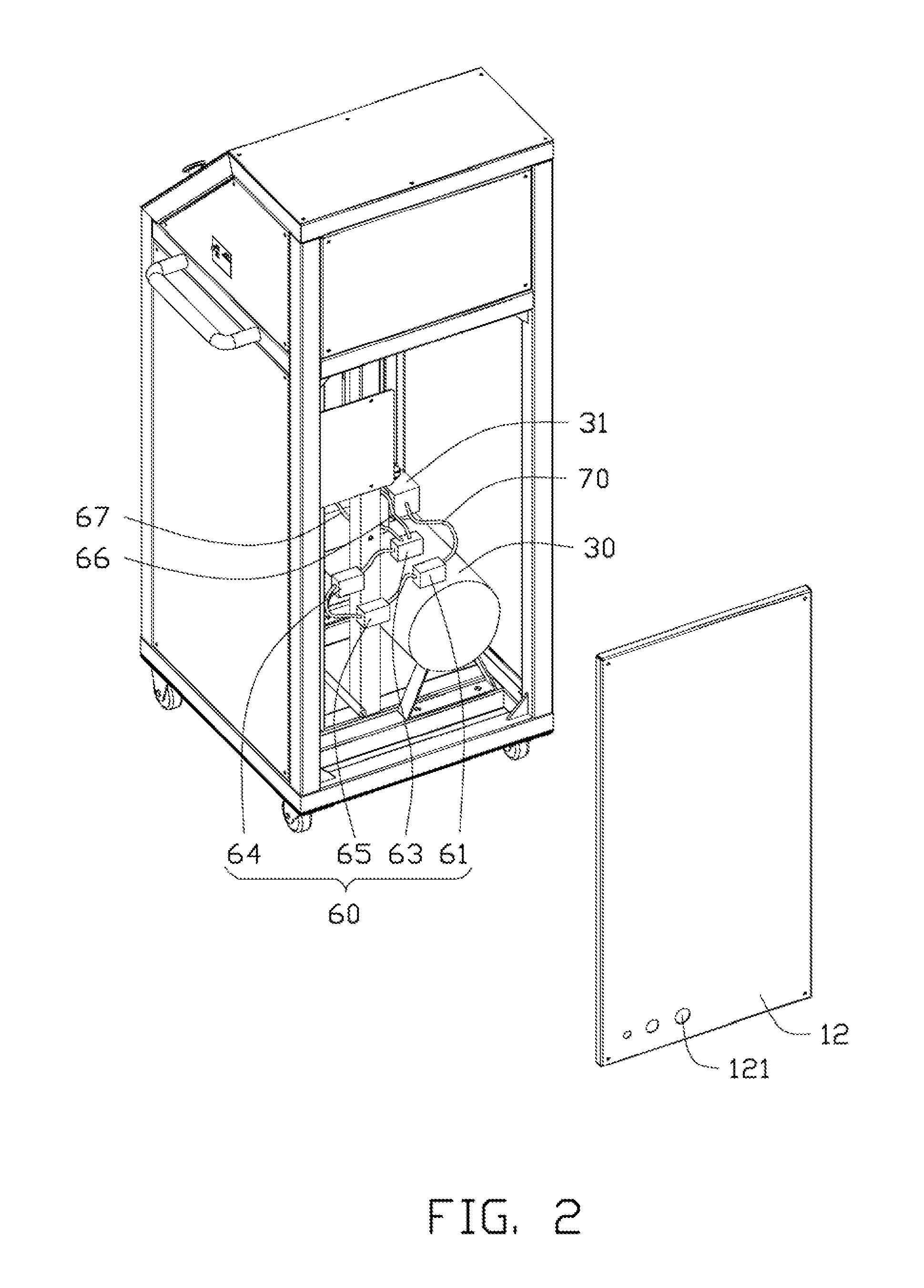
[0013]Referring to FIGS. 1 and 2, a pressure controlling system in accordance with an embodiment includes a power supply cabinet 10, a power controlling module 20, a pressurized cabinet 30, and a pressurized device 40 engaged with the pressurized cabinet 30.

[0014]The power supply cabinet 10 includes a door 11, a rear plate 12, and an operating panel 13 connected to the door 11. A through hole 121 is defined in the rear plate 12 for a gas pipe 16 (shown in FIG. 4) extending through. A plurality of displaying modules 131 are located on the operating panel 13. The plurality of displaying modules 131 can be an annunciator or one or more indicator lig...


PUM

PropertyMeasurementUnit
Pressureaaaaaaaaaa
Diameteraaaaaaaaaa

Abstract

A pressure controlling system includes a pressurized device, a piston device, and an electromagnetic routing valve. The pressurized device includes a moving cavity, and a receiving cavity adapted to receive liquid. A pipe is connected to the receiving cavity, and the pipe is adapted to connect a hydraulic cylinder plate. A connecting pipe, a noise elimination pipe, a first gas transmitting pipe, and a second gas transmitting pipe are connected to the electromagnetic routing valve. The first gas transmitting pipe and the second gas transmitting pipe are connected to the pressurized device.

Description

BACKGROUND[0001]1. Technical Field[0002]The present disclosure relates to a pressure controlling system and a pressure controlling method.[0003]2. Description of Related Art[0004]A gate is located on an end of a part made by injection molding. When injection molding of the part is completed, it is necessary to break the gate off from the part. However, the gate often has a large size and a lot of time may be required to remove and trim the gate off the part. Thus, removal of the gate may cause the injection molding process to be less efficient. Therefore, an improved system and method may be desired within the art.BRIEF DESCRIPTION OF THE DRAWINGS[0005]Many aspects of the embodiments can be better understood with reference to the following drawings. The components in the drawings are not necessarily drawn to scale, the emphasis instead being placed upon clearly illustrating the principles of the embodiments. Moreover, in the drawings, like reference numerals designate corresponding ...

Claims


Application Information

Patent Timeline
IPC IPC(8): F16K21/04
CPCB29C45/38F15B3/00B29C45/82Y10T137/7837Y10T137/0396
Inventor JIANG, FANGLI, FA-YEWU, SHUN-BAIZHOU, DAI-PINGWU, HAO-QUANTAN, PENGCHEN, CUI
Owner HONG FU JIN PRECISION IND (SHENZHEN) CO LTD
Why Eureka
Try Eureka