Distortion Free Stigmation of a TEM

a stigmation and distortion-free technology, applied in the field of distorsive particle apparatuses, can solve the problems of hysteresis, drift of image, and ld, and achieve the effect of reducing astigmatism and reducing astigmatism

Active Publication Date: 2013-03-14
FEI CO
View PDF8 Cites 15 Cited by
  • Summary
  • Abstract
  • Description
  • Claims
  • Application Information

AI Technical Summary

Benefits of technology

[0020]The invention relates to a charged particle apparatus equipped with a charged particle source for emitting a beam of charged particles, downstream of the beam are condenser optics, followed by a sample position, followed by an objective lens, followed by imaging optics, and followed by a detector system, in which, between the objective lens and the detector system, a first stigmator is positioned for reducing astigmatism when imaging a sample on the detector system and a second stigmator is positioned for reducing astigmatism when the diffraction plane is imaged on the detector system, and a third stigmator is positioned between the objective lens and the detector system, as a result of which a third degree of freedom is created for reducing the linear distortion.
[0021]The invention further relates to a method of using said three stigmators, the method comprising exciting the first stigmator to reduce astigmatism when imaging the sample, exciting the second stigmator to reduce astigmatism when imaging the diffraction plane, and exciting the third stigmator to reduce the linear distortion.

Problems solved by technology

A problem using one stigmator for correcting the astigmatism is that Linear Distortion (LD) arises: the magnification in two perpendicular directions may be different.
This can be caused by, for example, imperfections in the shape of the objective lens.
A problem arises when using two stigmators to correct astigmatism in the two modes (imaging mode and diffraction mode) and also correct for LD with those stigmators: when switching between modes, also the excitation of the stigmators must be changed.
The change in excitation causes a different ohmic heat production in the coils of the stigmator, typically a change of several watt, resulting in drift of the image due to the resultant temperature drift.
Also hysteresis may occur, especially when iron yokes are used.

Method used


Image

  • Distortion Free Stigmation of a TEM
  • Distortion Free Stigmation of a TEM
  • Distortion Free Stigmation of a TEM

Examples


Embodiment Construction

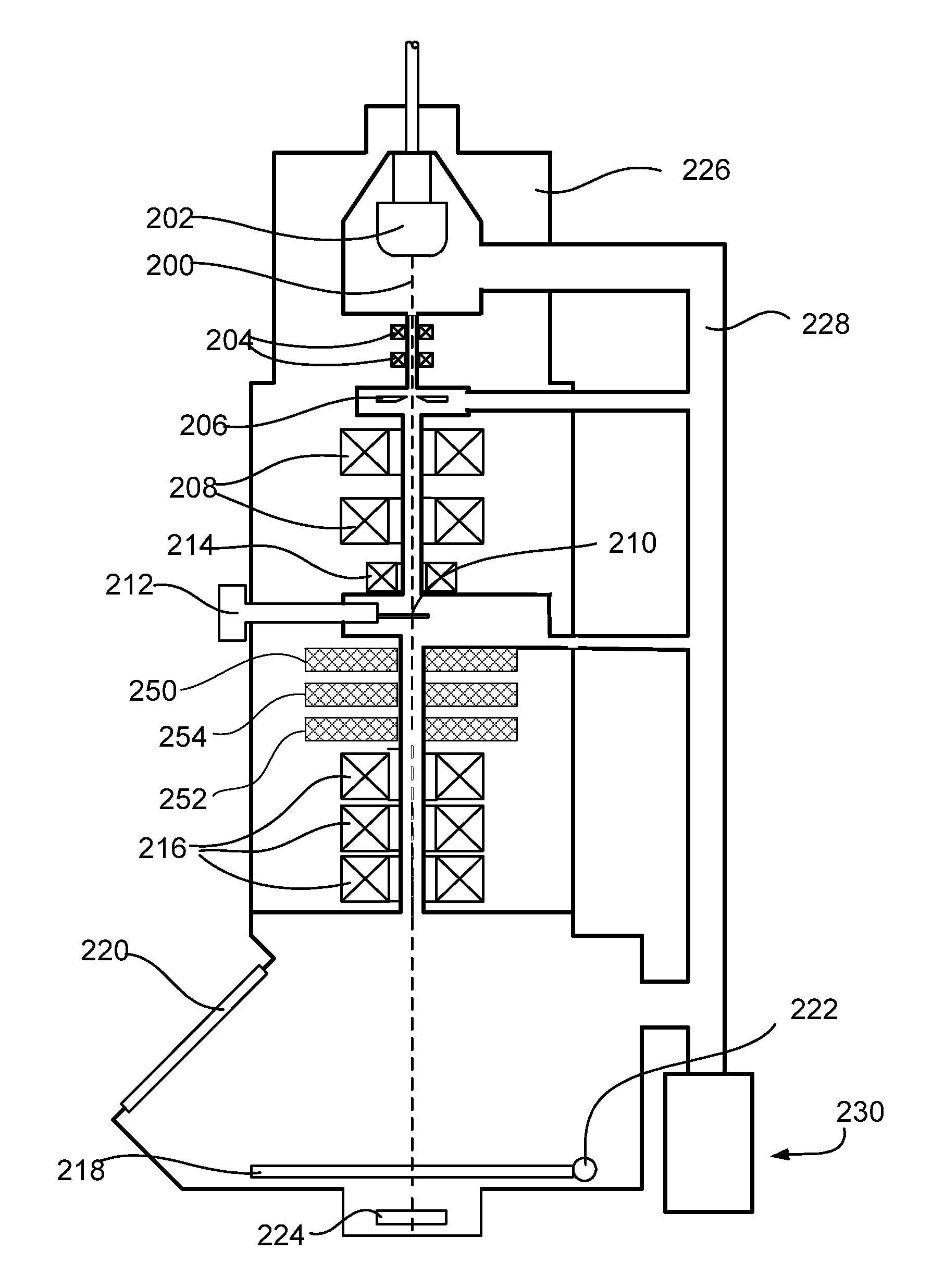
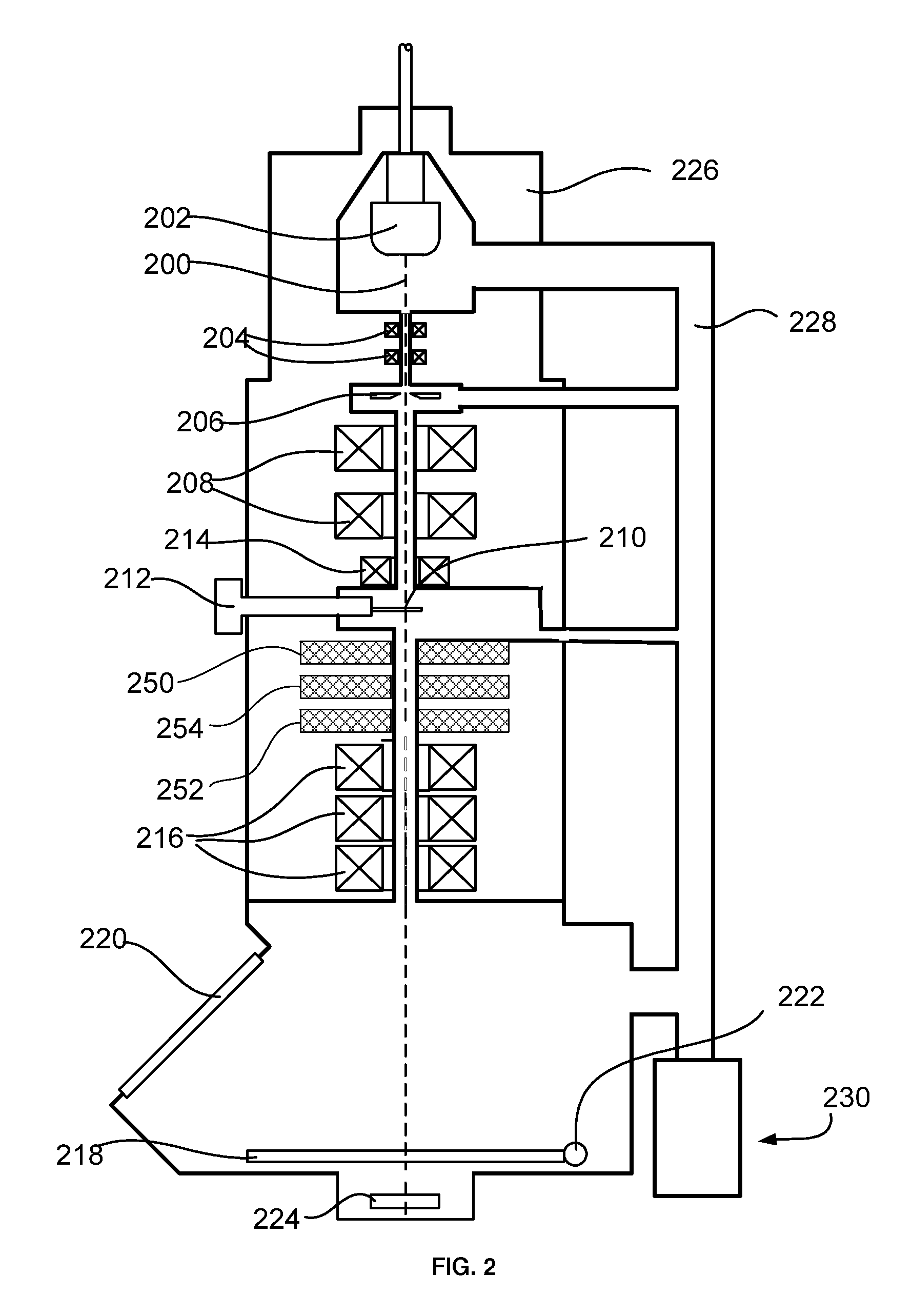
[0028]A TEM according to the invention is characterized in that a third stigmator is positioned between the objective lens and the detector system, as a result of which a third degree of freedom is created for reducing the linear distortion.

[0029]The invention is based on the insight that it is possible to excite three stigmators in such a manner that astigmatism in both modes (imaging mode and diffraction mode) is possible without Linear Distortion. Therefore also no dissipation changes occur, and thus no drift is introduced by change of stigmator dissipation. It will be clear to the person skilled in the art that the stigmators should not be imaged upon each other: it should be an independent set of stigmators

[0030]Preferably the three stigmators are placed between the objective lens and the imaging optics. The magnification of the imaging optics can then be changed without having to change stigmator excitation, as all lenses of the imaging optics are between the stigmators and th...


PUM


Abstract

A charged particle apparatus is equipped with a third stigmator positioned between the objective lens and a detector system, as a result of which a third degree of freedom is created for reducing the linear distortion.Further, a method of using said three stigmators, comprises exciting the first stigmator to reduce astigmatism when imaging the sample, exciting the second stigmator to reduce astigmatism when imaging the diffraction plane, and exciting the third stigmator to reduce the linear distortion.

Description

[0001]This Application claims priority from U.S. Provisional Application 61 / 475,117, filed Apr. 13, 2011, which is hereby incorporated by reference.TECHNICAL FIELD OF THE INVENTION[0002]The invention relates to a charged particle apparatus equipped for reducing astigmatism and distortion, and method thereof.BACKGROUND OF THE INVENTION[0003]In a TEM a sample, such as a thin slice of biological material or a thin slice of semiconductor material, with a thickness of typically between 2 nm to 1 μm, is irradiated with an energetic beam of electrons. The energy of the electrons is, for example, adjustable between 50 to 400 keV, although TEMs using a higher and / or lower energy are known to be used. The sample is placed in or near the objective lens of the TEM, so that the objective lens forms a first image of the sample with a magnification of, for example, 20 times.[0004]As known to the skilled artisan a TEM has two major modes of operation, one in which the sample is imaged on the detect...

Claims


Application Information

Patent Timeline
Patent Type & Authority Applications(United States)
IPC IPC(8): H01J3/14H01J37/26
CPCH01J37/153H01J2237/1532H01J37/26
Inventor HENSTRA, ALEXANDERBISCHOFF, MAARTENLUECKEN, UWETIEMEIJER, PETER CHRISTIAAN
Owner FEI CO
Why Eureka
Try Eureka