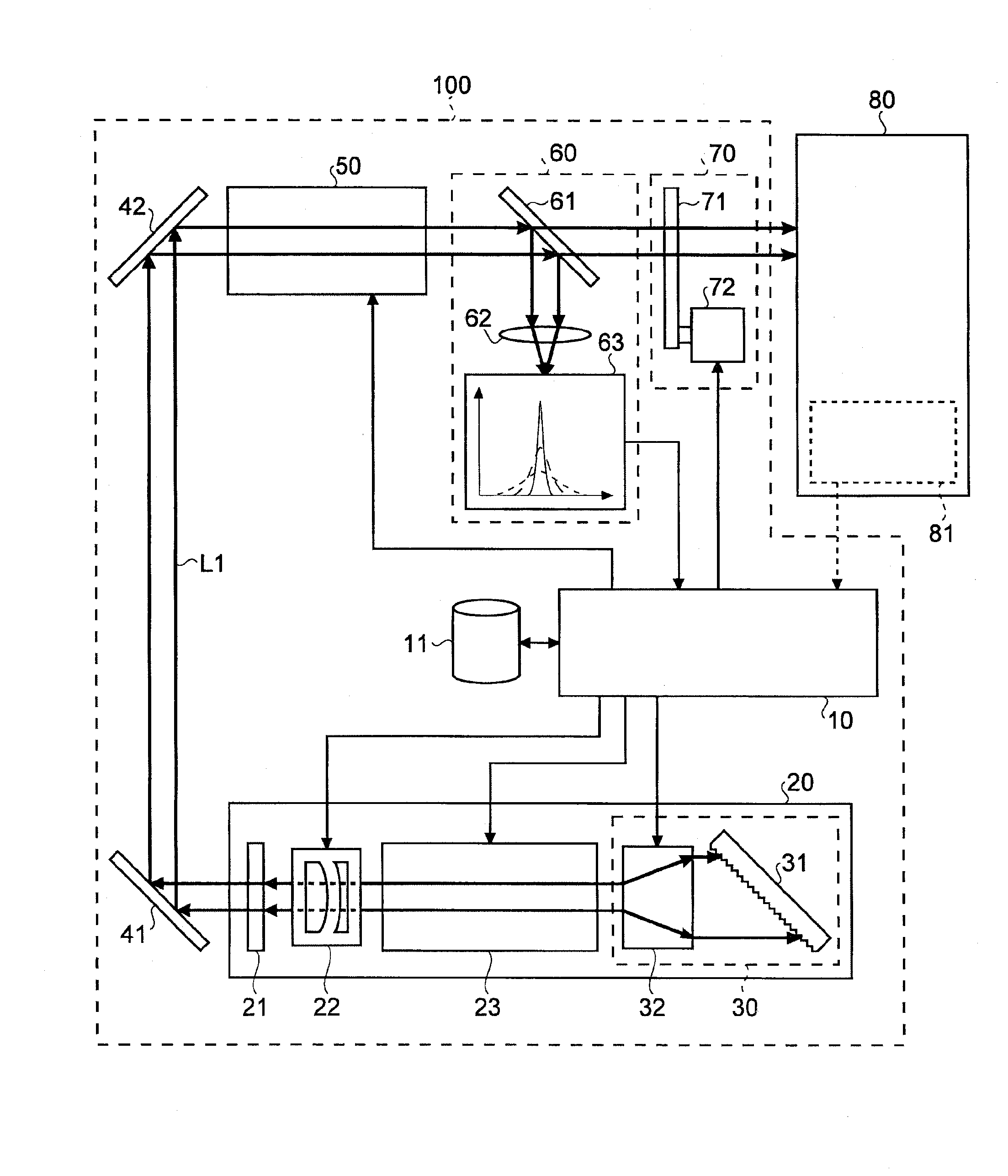
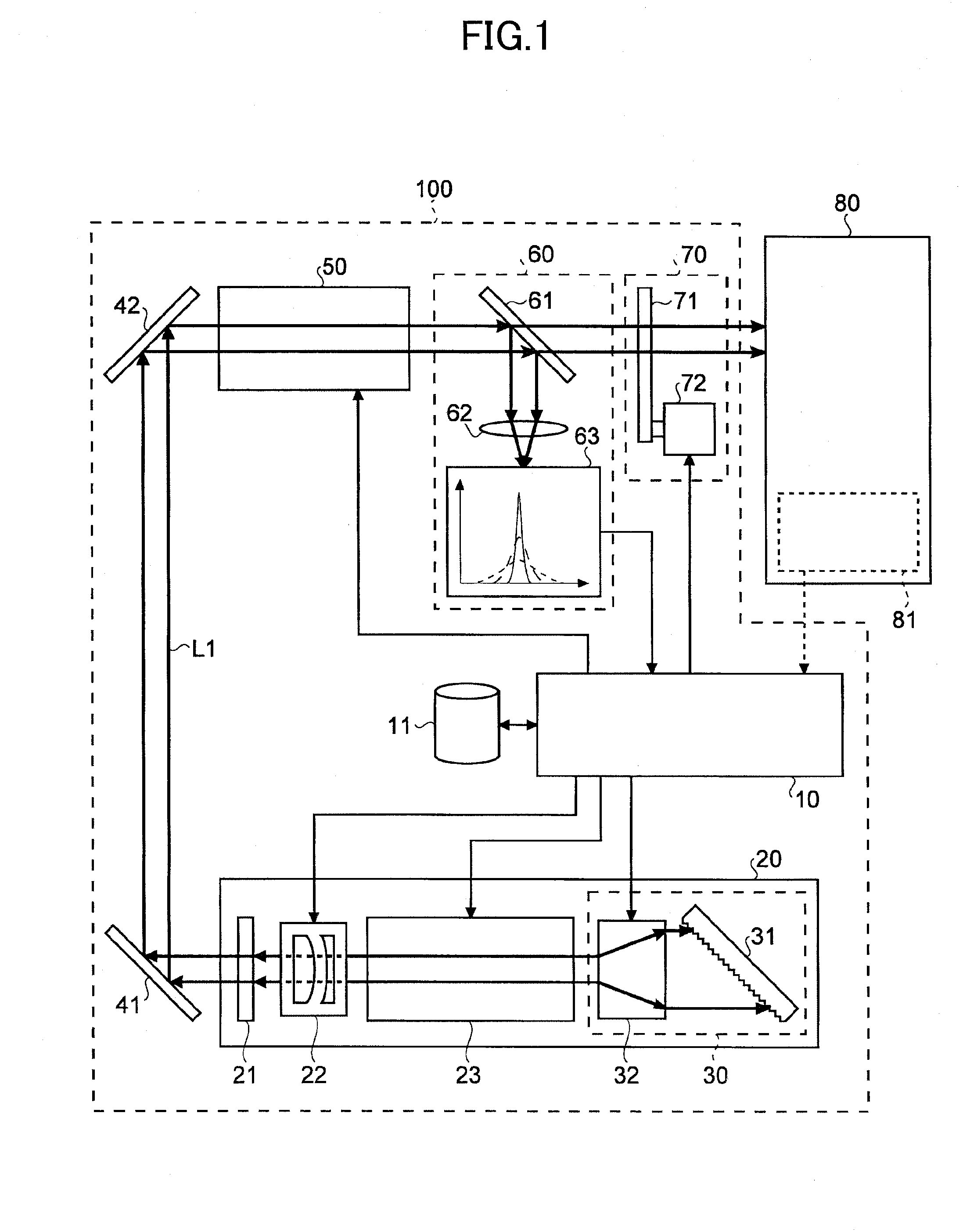
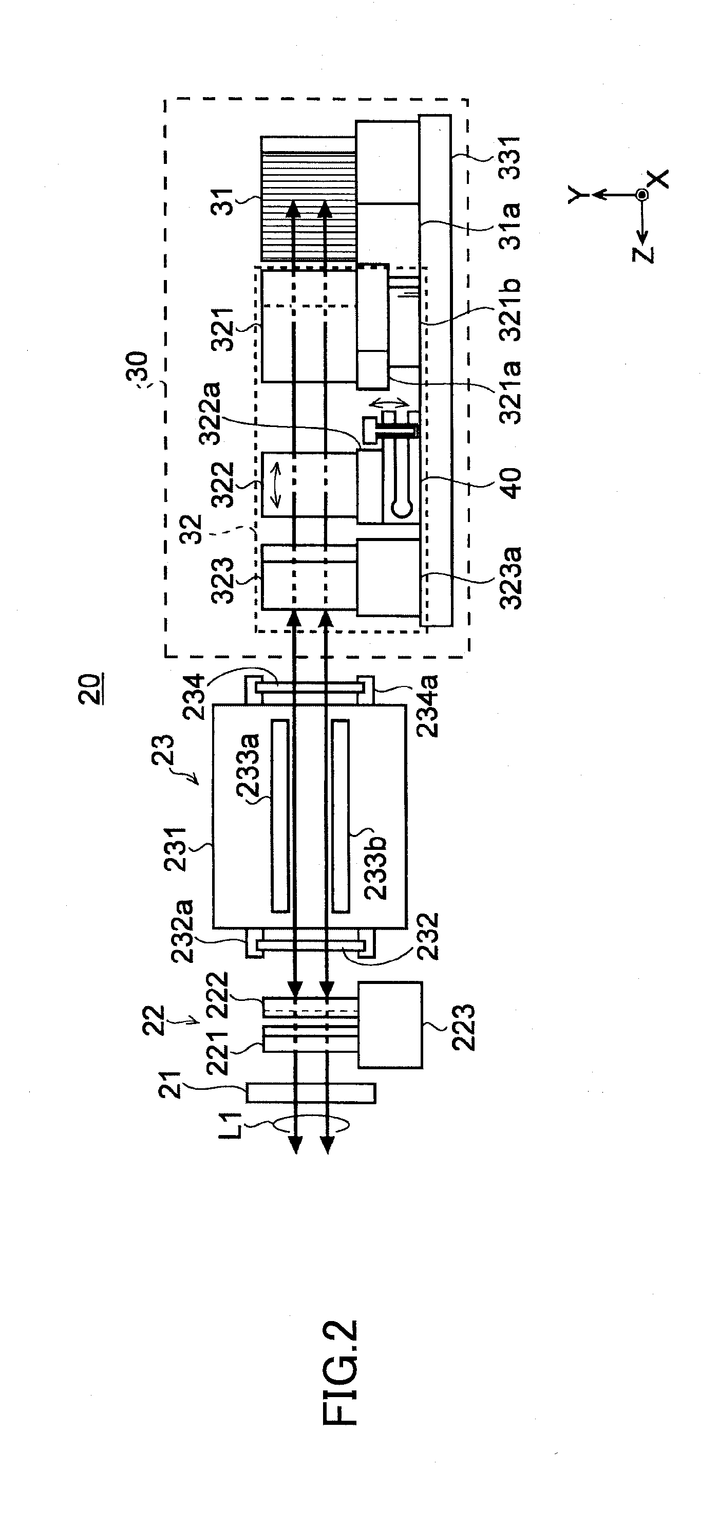
Master oscillator system and laser apparatus
a laser apparatus and oscillator technology, applied in the direction of laser details, electrical apparatus, wave amplification devices, etc., can solve problems such as drop in resolution
- Summary
- Abstract
- Description
- Claims
- Application Information
AI Technical Summary
Benefits of technology
Problems solved by technology
Method used
Image
Examples
first example
[0073]4.1.1.1.1 First Example
[0074]FIGS. 4 and 5 schematically illustrate the configuration of the attitude control mechanism 40 according to a first example. FIG. 4 is a cross-sectional view of the attitude control mechanism 40, seen from the side. FIG. 5 is a top view of the attitude control mechanism 40. FIG. 6 illustrates a relationship between a rotational axis AX of the prism 322 and entry / exit surfaces of the laser light L1.
[0075]As shown in FIGS. 4 and 5, the attitude control mechanism 40 may include an attitude adjustment plate 43, configured of a flat plate bent into a U shape, and two bolts 44 and 45. The attitude adjustment plate 43 may include two plate portions 43a and 43b disposed approximately parallel to and at a distance from each other. The plate portions 43a and 43b may be connected at one end via a connection portion 43c. The connection portion 43c maybe configured so that part thereof is thinner than other parts in order to reduce the rigidity of that part.
[007...
second example
[0103]4.1.2.2 Second Example
[0104]FIG. 12 schematically illustrates the configuration of a master oscillator system 20B according to a second example that includes a mechanism that changes a magnification rate by replacing prisms. As shown in FIG. 12, the master oscillator system 20B may have the same configuration as the master oscillator system 20A shown in FIG. 9, but with a line narrow module 30B replacing the line narrow module 30A. The line narrow module 30B, meanwhile, may have the same configuration as the line narrow module 30A, but with a beam width tuning unit 32B replacing the beam width tuning unit 32A.
[0105]The beam width tuning unit 32B may have the same configuration as the beam width tuning unit 32A, but with beam width tuners 303-3a and 303-3b replacing the beam width tuners 303-1 and 303-2. The number of beam width tuners is not limited to two, and more maybe provided. Meanwhile, each of the beam width tuners 303-3a and 303-3b may include an attitude control mecha...
third example
[0121]4.1.2.3 Third Example
[0122]Next, a third example of the master oscillator system 20 illustrated in FIG. 1 will be described in detail with reference to the drawings. In the third example, the optical path tuning prism 321 that tunes the optical path through which the laser light L1 is incident on the grating 31 may be used in the beam width tuning unit. FIG. 15 schematically illustrates the configuration of a master oscillator system 20C according to the third example. As shown in FIG. 15, the master oscillator system 20C may have the same configuration as the master oscillator system 20A shown in FIG. 9, but with a line narrow module 30C replacing the line narrow module 30A. The line narrow module 30C may omit the optical path tuning prism 321 immediately before the grating 31 and may replace the beam width tuning unit 32A with a beam width tuning unit 32C.
[0123]As shown in FIG. 15, the beam width tuning unit 32C may include a plurality of optical path tuning prisms 36a and 3...
PUM
 Abstract
Description
Claims
Application Information
 - R&D
- Intellectual Property
- Life Sciences
- Materials
- Tech Scout
- Unparalleled Data Quality
- Higher Quality Content
- 60% Fewer Hallucinations
Browse by: Latest US Patents, China's latest patents, Technical Efficacy Thesaurus, Application Domain, Technology Topic, Popular Technical Reports.
© 2025 PatSnap. All rights reserved.Legal|Privacy policy|Modern Slavery Act Transparency Statement|Sitemap|About US| Contact US: help@patsnap.com


