Fan grill for a mosquito trap

Inactive Publication Date: 2013-03-14
INVICTUS INT
View PDF7 Cites 12 Cited by
  • Summary
  • Abstract
  • Description
  • Claims
  • Application Information

AI Technical Summary

Benefits of technology

[0009]The main object of the present invention is to provide a fan grill for a mosquito trap t

Problems solved by technology

However, the fan grill 60 with multiple circular air holes 611 has a greater resistance to airflow so that the airflow created

Method used


Image

  • Fan grill for a mosquito trap
  • Fan grill for a mosquito trap
  • Fan grill for a mosquito trap

Examples


Example

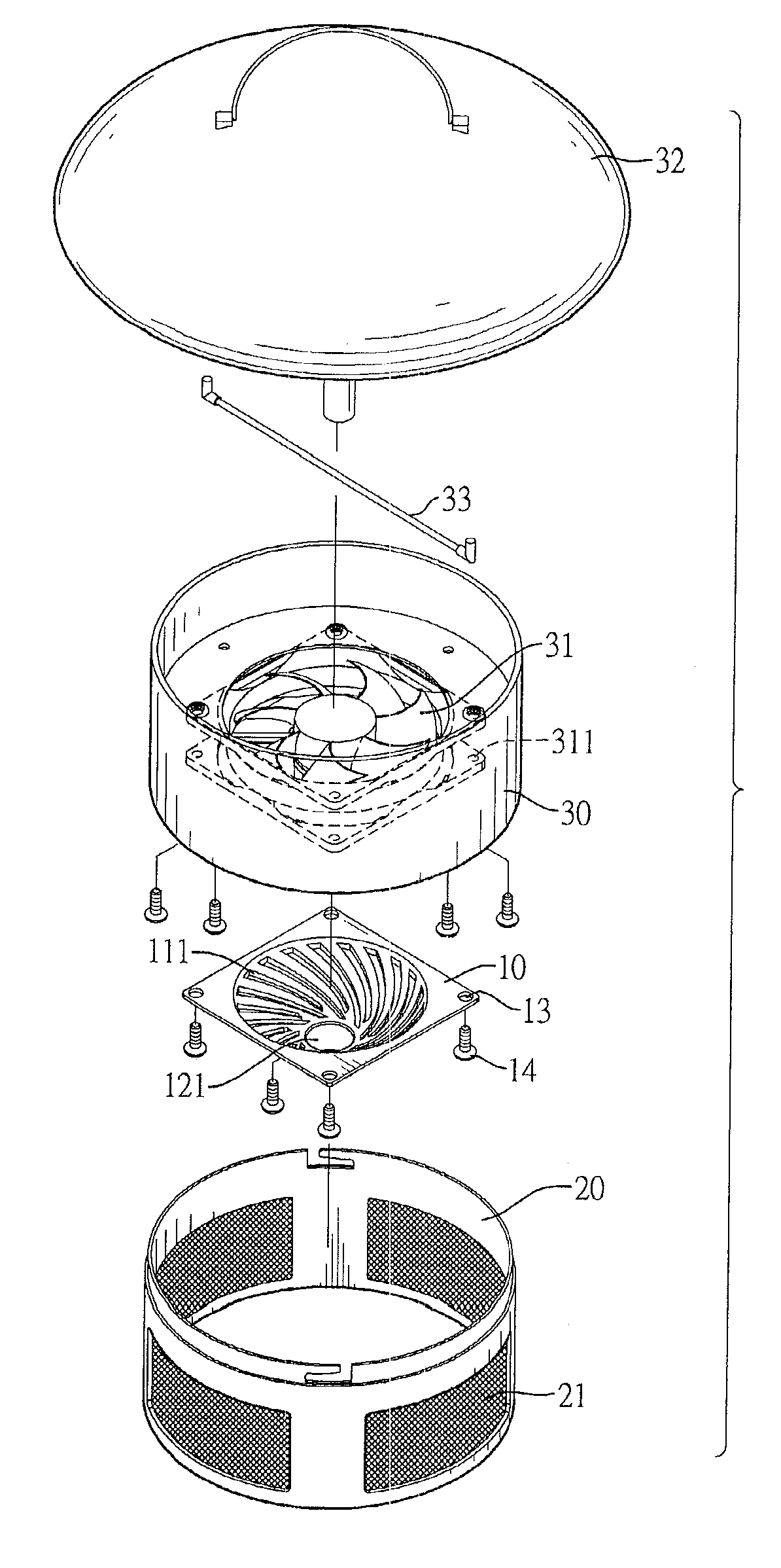
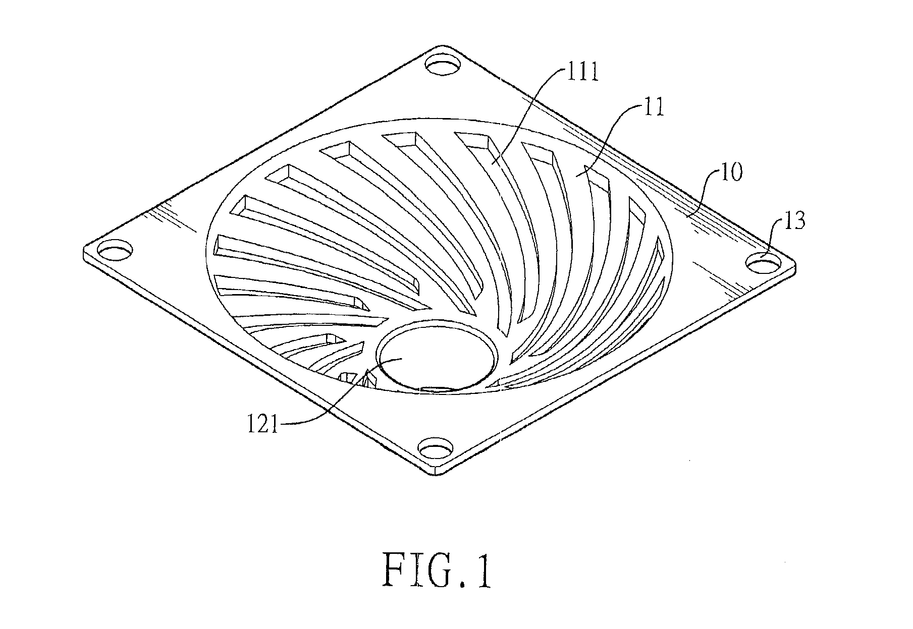
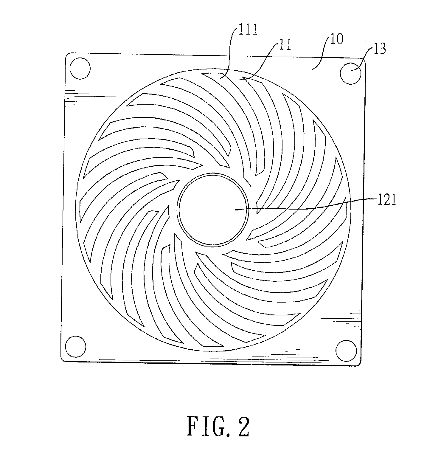
[0025]With reference to FIGS. 1 to 3, a fan grill in accordance with the present invention is a rectangular board 10 and comprises a center, a funnel-shaped shell 11, multiple air holes 111 and a tube 12. The shell 11 is formed downward in the center and is tapered off to a bottom. The air holes 111 are respectively formed through the shell 11 and are arranged radially and spirally. Hole diameters of the air holes 111 are less than sizes of mosquitoes. The tube 12 is formed on and protrudes from the bottom of the shell 11 and includes a through hole 121 communicating with an interior of the shell 11. In a preferred embodiment, the air holes 111 extend radially and spirally outward from the through hole 121 serving as a center, the air holes 111 are curved and elongated and widths of the elongated air holes 111 are less than sizes of mosquitoes. Further, the fan grill may comprise four fastening holes 13 respectively formed through four corners of the board 10.

[0026]With reference to...


PUM


Abstract

A fan grill for a mosquito trap is a board and has a center, a funnel-shaped shell, multiple air holes and a through hole. The shell is formed downward in the center and is tapered off to a bottom. The air holes are respectively formed through the shell and are arranged radially and spirally. The through hole is formed on the bottom of the shell. The radial and spiral air holes are designed according to direction of airflow created by a fan so allow the airflow to pass smoothly therethrough and to generate steady suction forces. Besides, hole diameters of the air holes are less than sizes of mosquitoes so trapped mosquitoes are prevented from escaping from between fan blades of the fan. Therefore, trapping efficiency is enhanced.

Description

BACKGROUND OF THE INVENTION[0001]1. Field of the Invention[0002]The present invention relates to a mosquito trap, and more particularly to a fan grill for a mosquito trap that can prevent trapped mosquitoes from escaping and allow airflow to pass smoothly therethrough.[0003]2. Description of the Prior Arts[0004]Mosquito traps are used to attract, trap and kill mosquitoes. With reference to FIGS. 10 and 11, a conventional mosquito trap comprises a mosquito collection box 40, a mounting bracket 50 and a cover 52. The mosquito collection box 40 includes an annular sidewall and filter screens 41 mounted on the annular sidewall. The mounting bracket 50 is mounted over the mosquito collection box 40 and includes a fan 51 therein. The cover 52 is mounted over the mounting bracket 50 and includes a bottom surface and a photocatalytic lamp tube 53 mounted on the bottom surface.[0005]When the mosquito trap is actuated, the photocatalytic lamp tube 53 is lighted and the fan 51 generates negati...

Claims


Application Information

Patent Timeline
IPC IPC(8): F01D25/00
CPCA01M1/06
Inventor TSAI, YI-YI
Owner INVICTUS INT
Why Eureka
Try Eureka