Intelligent laser tracking system and method for mobile and fixed position traffic monitoring and enforcement applications

a laser tracking and mobile and fixed position technology, applied in the field of intelligent laser tracking system and mobile and fixed position traffic monitoring and enforcement applications, can solve the problems of not being able to be employed in autonomous applications, unable to divert his attention from that function, etc., to achieve accurate tracking of target vehicles, minimize inertia, and high torque and efficiency

Active Publication Date: 2013-03-14
LASER TECH INC +1
View PDF12 Cites 25 Cited by
  • Summary
  • Abstract
  • Description
  • Claims
  • Application Information

AI Technical Summary

Benefits of technology

[0010]The system of the present invention provides extremely accurate tracking of target vehicles using a novel and extremely fast pan / tilt mechanism which is stabilized through the use of an onboard gyro and inclinometer. The pan / tilt mechanism utilizes respective pan and tilt brushless DC (BLDC) motors which provide high torque and efficiency. The relatively heavy motors are mounted to the pan / tilt mechanism base plate to minimize inertia and lower the mass of the moving pan and tilt plates to which the laser rangefinder of the high performance laser speed measurement subsystem and the visual sensor subsystem are affixed.
[0011]In a mobile implementation of the present invention, the police vehicle in which the system is mounted has its own speed uploaded to the system via the vehicle's onboard diagnostic (OBD II) controller area network (CAN) port. Increased accuracy of this information is assured through updating of the police vehicle's speed through appropriate application of a global positioning system (GPS) subsystem to correct speed data for tire wear and pressure. Conveniently, the system of the present invention can be mounted within a standard police vehicle light bar enclosure or in other locations to provide both a forward and rearward view of traffic.
[0012]The intelligent laser tracking system of the present invention also assures that the laser is consistently aimed at a single specific point on the target vehicle to obviate geometric errors. Moreover, the system and method of the present invention can accurately compensate for the cosine effect when the target vehicle is moving at an angle with respect to the system.
[0013]In addition to mobile embodiments of the present invention for use in a police vehicle, the system of the present invention can also be mounted on a tripod or other fixture in a fixed or stationary location adjacent one or more lanes of vehicle traffic while still providing accurate targeting of multiple target vehicle speeds, distances and angles.

Problems solved by technology

That being the case, they have not been able to be employed in autonomous applications wherein an operator is not manually aiming the device.
Further, in mobile applications wherein the officer may be driving a vehicle himself, he is then unable to divert his attention from that function in order to track and aim a laser based speed measurement device at a suspected speeder let alone track multiple targets.

Method used


Image

  • Intelligent laser tracking system and method for mobile and fixed position traffic monitoring and enforcement applications
  • Intelligent laser tracking system and method for mobile and fixed position traffic monitoring and enforcement applications
  • Intelligent laser tracking system and method for mobile and fixed position traffic monitoring and enforcement applications

Examples


Embodiment Construction

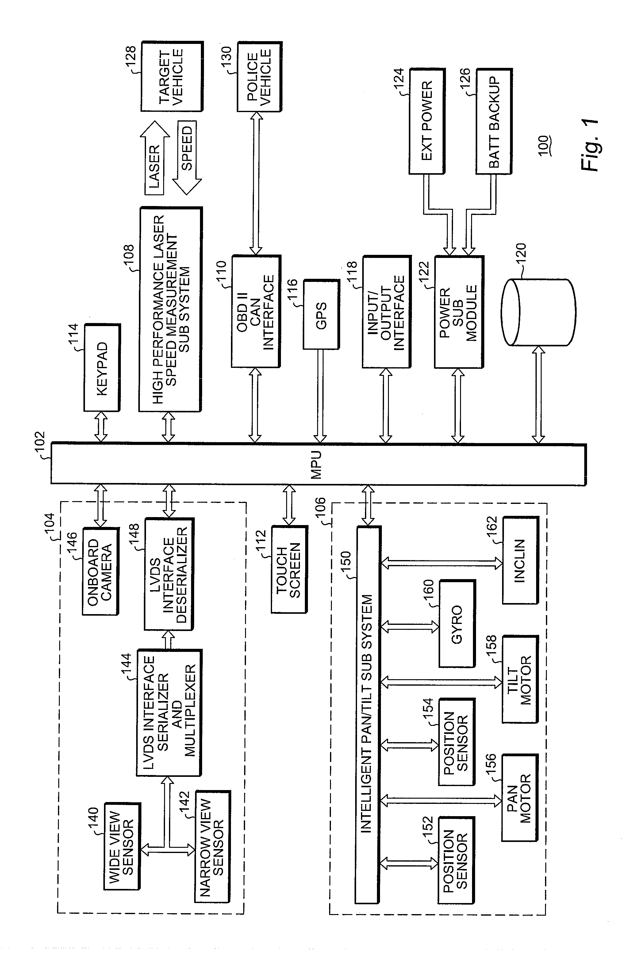
[0031]With reference now to FIG. 1, a high level functional block diagram of a representative embodiment of the intelligent laser tracking system for mobile traffic monitoring and enforcement applications of the present invention is shown. The system 100 comprises a central processing unit (CPU), microcontroller (MCU) or microprocessor (MPU) 102 which, in a representative embodiment, may comprise one of the 600 MHz OMAP 34xx, 35xx or 36xx series of high performance application processors available from Texas Instruments, Inc.

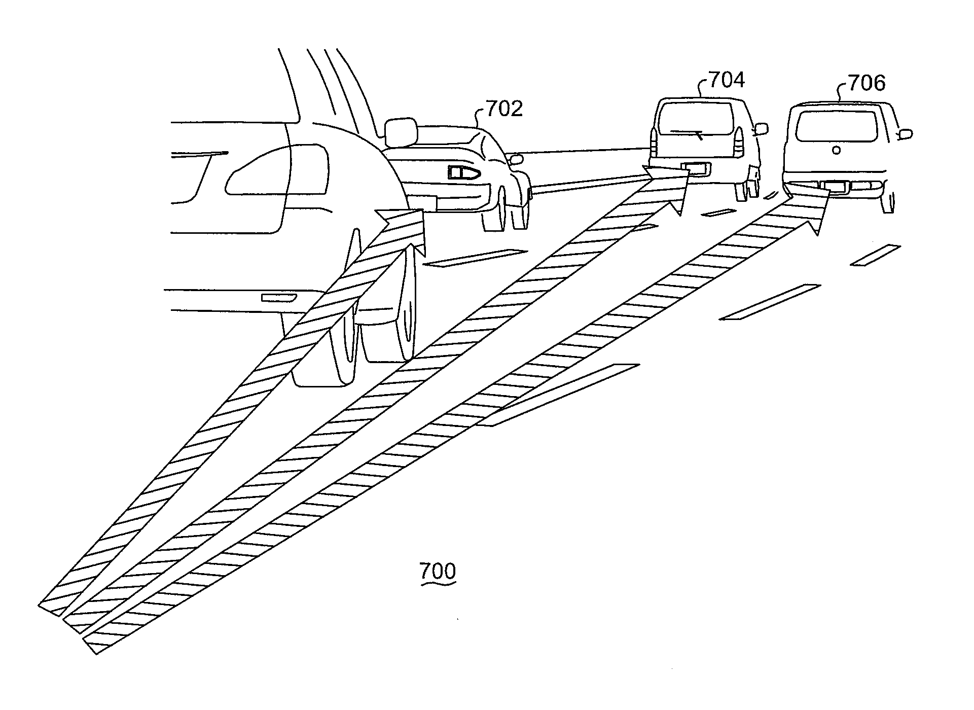
[0032]A visual sensor subsystem 104 is bidirectionally coupled to the MPU 102 by one or more image buses as illustrated to which an intelligent pan / tilt subsystem 106 is also bidirectionally coupled. The visual sensor subsystem 104 may be made physically detachable from the rest of the unit if desired. A high performance laser speed measurement subsystem 108 is also bidirectionally coupled to the MPU 102 to provide distance and speed measurement data between the...


PUM


Abstract

An intelligent laser tracking system and method for mobile and fixed position traffic monitoring and enforcement applications. The system disclosed herein can autonomously track multiple target vehicles with a highly accurate laser based speed measurement system or, under manual control via a touch screen, select a particular target vehicle of interest. In a mobile application the police vehicle speed is determined through the OBD II CAN port and updated for accuracy though an onboard GPS subsystem. The system and method of the present invention simultaneously provides both narrow and wide images of a target vehicle for enhanced evidentiary purposes. A novel, low inertia pan / tilt mechanism provides extremely fast and accurate target vehicle tracking and can compensate for geometrical errors and the cosine effect.

Description

COPYRIGHT NOTICE / PERMISSION[0001]A portion of the disclosure of this patent document contains material which is subject to copyright protection. The copyright owner has no objection to the facsimile reproduction by anyone of the patent document of the patent disclosure as it appears in the United States Patent and Trademark Office patent file or records, but otherwise, reserves all copyright rights whatsoever. The following notice applies to the pseudo code described herein, inclusive of the drawing figures where applicable: Copyright© 2011, Laser Technology, Inc.BACKGROUND OF THE INVENTION[0002]The present invention relates, in general, to the field of traffic monitoring and enforcement systems. More particularly, the present invention relates to an intelligent laser tracking system and method for mobile and fixed position traffic monitoring and enforcement applications.[0003]Police have been using radar and laser speed measurement devices to determine vehicle speed in traffic enfo...

Claims


Application Information

Patent Timeline
Patent Type & Authority Applications(United States)
IPC IPC(8): G08G1/052G08G1/04
CPCG08G1/04G08G1/054G08G1/052
Inventor CHUNG, JIYOON
Owner LASER TECH INC
Why Eureka
Try Eureka