
Handheld Medical Devices Including Microwave Amplifier Unit At Device Handle

a technology of microwave amplifier and hand-held medical devices, which is applied in the field of hand-held medical devices, can solve the problems of affecting the surgeon's full freedom of movement, the cost of cable assemblies, and the interference of wireless networks deployed, so as to facilitate cleaning and/or serialization

Inactive Publication Date: 2013-03-21
TYCO HEALTHCARE GRP LP
View PDF2 Cites 39 Cited by
  • Summary
  • Abstract
  • Description
  • Claims
  • Application Information

AI Technical Summary

Benefits of technology

The patent describes a medical device that includes a handle assembly and a probe-and-amplifier assembly. The handle assembly has a microwave amplifier unit disposed within it, and the probe-and-amplifier assembly includes a probe that extends from the handle assembly. The microwave amplifier unit is adapted to amplify a high-frequency input signal and generate a high-frequency output signal for transmission to the probe. The handle assembly can be adapted to allow the microwave amplifier unit to be removable from it. The technical effects of this design include the ability to easily clean and replace the probe without having to replace the entire device, as well as the ability to switch between different signal sources for high-frequency signals.

Problems solved by technology

Stray leakage of microwave energy from the cable assembly may cause interference to deployed wireless networks, patient monitoring, and other medical equipment used in a hospital environment.
Cable assemblies add cost to produce and maintain the microwave surgical instruments.
Cable assemblies may also interfere with the surgeon's full freedom of movement during use of a handheld instrument to perform procedures utilizing electromagnetic radiation to treat tissue.

Method used


Image

  • Handheld Medical Devices Including Microwave Amplifier Unit At Device Handle
  • Handheld Medical Devices Including Microwave Amplifier Unit At Device Handle
  • Handheld Medical Devices Including Microwave Amplifier Unit At Device Handle

Examples


Embodiment Construction

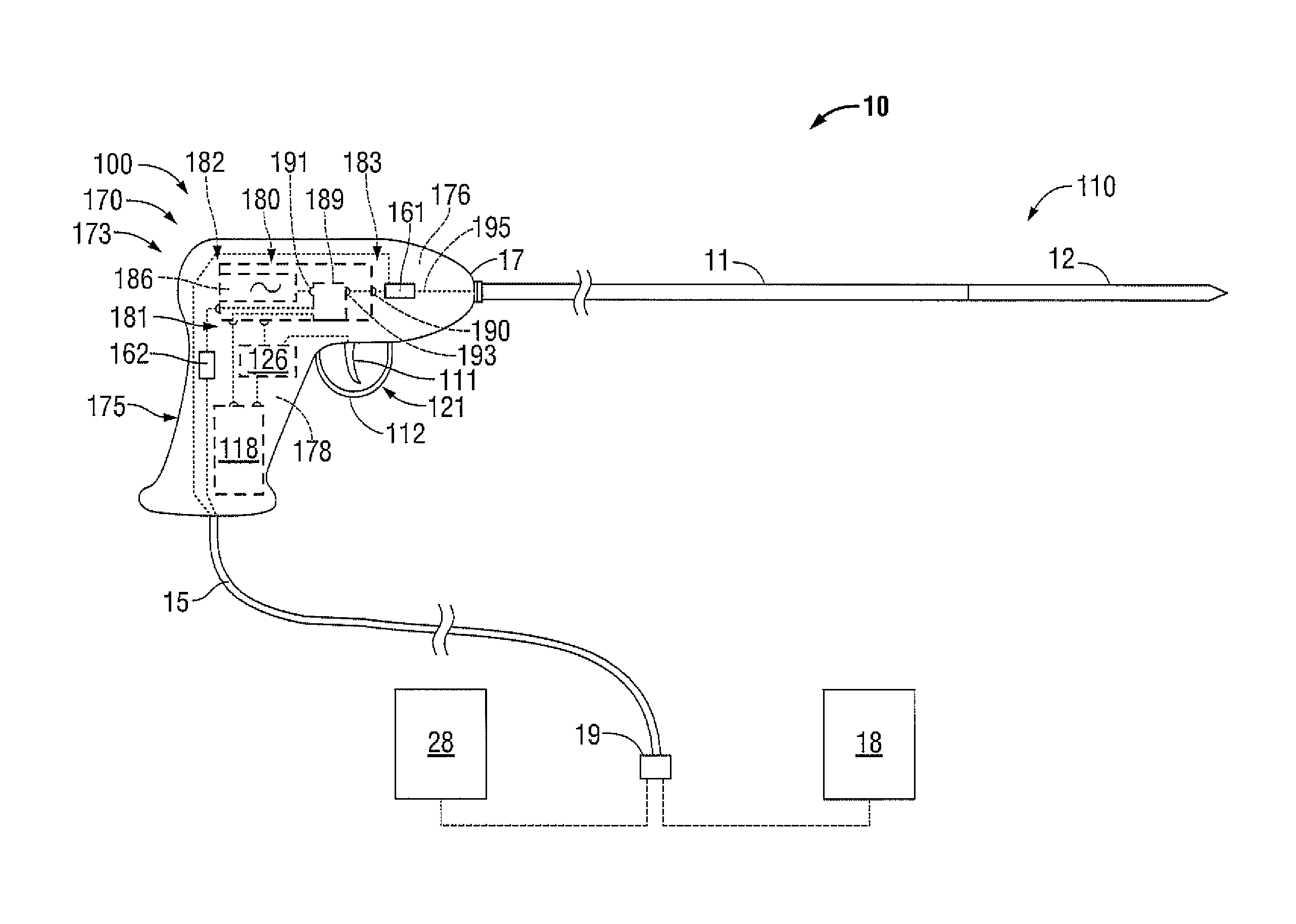
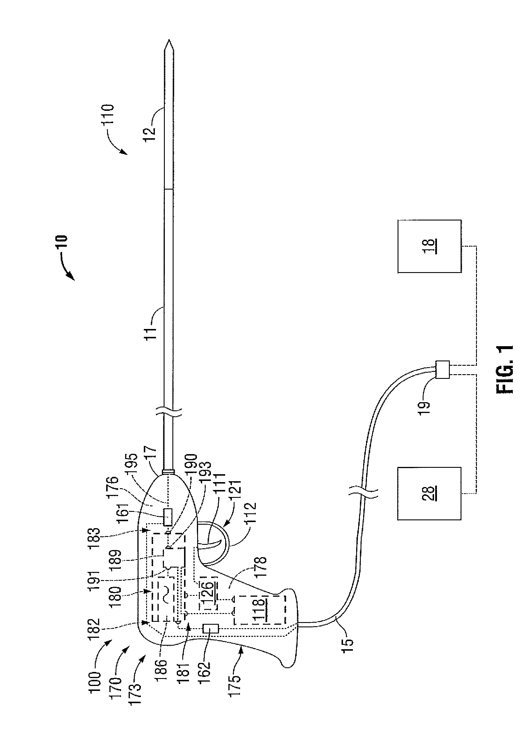
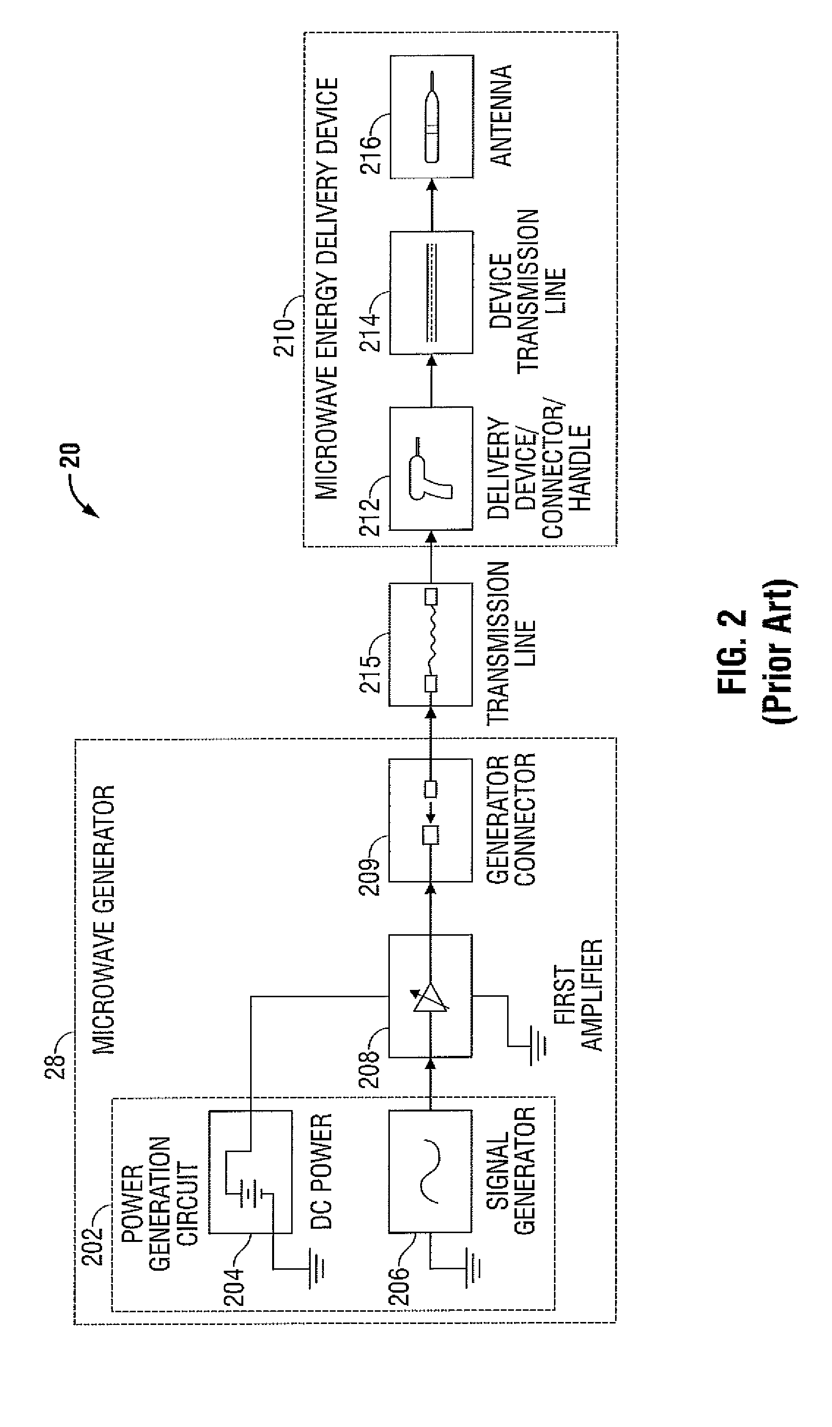
[0039]Hereinafter, embodiments of the presently-disclosed handheld medical device with a microwave amplifier unit at the device handle, electrosurgical systems including the same, methods of directing energy to tissue using the same, and methods of manufacturing the same will be described with reference to the accompanying drawings. Like reference numerals may refer to similar or identical elements throughout the description of the figures. As shown in the drawings and as used in this description, and as is traditional when referring to relative positioning on an object, the term “proximal” refers to that portion of the apparatus, or component thereof, closer to the user and the term “distal” refers to that portion of the apparatus, or component thereof, farther from the user. In the following description, well-known functions or constructions are not described in detail to avoid obscuring the present disclosure in unnecessary detail.

[0040]This description may use the phrases “in an...


PUM

PropertyMeasurementUnit
temperatureaaaaaaaaaa
frequencyaaaaaaaaaa
frequencyaaaaaaaaaa

Abstract

A method of manufacturing a medical device includes the initial steps of providing a handle assembly and providing a microwave-signal-amplifying module. The handle assembly includes a handle body defining a chamber therein. The handle body is configured to support an energy applicator at the distal end thereof. The microwave-signal-amplifying module includes a microwave amplifier unit adapted to amplify a high-frequency input signal to generate a high-frequency output signal. The microwave-signal-amplifying module includes one or more connector portions including one or more electrical connectors adapted to be removeably coupleable to one or more electrical conductors associated with the handle body. The method also includes the step of positioning the microwave-signal-amplifying module into the chamber to bring the one or more electrical connectors of the one or more connector portions into electrical engagement with one or more electrical connectors associated with the handle body.

Description

BACKGROUND[0001]1. Technical Field[0002]The present disclosure relates to handheld medical devices suitable for use in tissue ablation applications. More particularly, the present disclosure relates to medical devices with a microwave amplifier unit at the device handle, electrosurgical systems including the same, methods of directing energy to tissue using the same, and methods of manufacturing the same.[0003]2. Discussion of Related Art[0004]Electrosurgical instruments have become widely used by surgeons. Electrosurgery involves the application of thermal and / or electrical energy to cut, dissect, ablate, coagulate, cauterize, seal or otherwise treat biological tissue during a surgical procedure. Electrosurgery is typically performed using a handpiece including a surgical instrument (e.g., end effector or ablation probe) adapted to transmit energy to a tissue site during electrosurgical procedures, a remote electrosurgical generator operable to output energy, and a cable assembly o...

Claims


Application Information

Patent Timeline
Patent Type & Authority Applications(United States)
IPC IPC(8): H05K13/00
CPCY10T29/49117Y10T29/49002A61B2019/4836A61B18/1815A61B2018/1823A61B2018/00922A61B2090/0807
Inventor BEHNKE, II, ROBERT J.JENSEN, JEFFREY L.FRUSHOUR, SCOTT E.M.MOUL, WAYNE L.
Owner TYCO HEALTHCARE GRP LP
Learn More