Heat exchanger for cooling charge air

Inactive Publication Date: 2013-03-21
MAHLE INT GMBH
View PDF13 Cites 5 Cited by
  • Summary
  • Abstract
  • Description
  • Claims
  • Application Information

AI Technical Summary

Benefits of technology

The present invention provides a flexible area or low-stiffness area between two areas with different thermal expansions to prevent damage from stress peaks in sensitive joints or thin-walled parts. This flexible area can deform permanently to protect joints and can be used to increase the lifetime of heat exchangers. A reduction of the installation space and pressure drop can also be achieved, resulting in better handling, reduced part lifetime, and reduced sealing requirements. The compensating component can have an overlapping plate or side plate to delimit the heat transfer region and compensate for position differences between components. This invention makes heat exchangers easier to use and protects sensitive components.

Problems solved by technology

More highly supercharged passenger vehicle engines result in constantly rising requirements for charge air cooling.
At the same time, the requirements within the scope of the charge air cooling become increasingly greater for a low charge air pressure drop and small packaging, therefore a small installation space.
Conventional single-stage charge air cooling with a coolant circuit has a limited cooling performance due to the low-temperature circuit or the low-temperature coolant cooler.
The different temperatures in the high-temperature or low-temperature cooling circuits cause different thermal expansions in both coolant stages, which in turn without further measures can lead to uncontrolled damage to the one-piece charge air cooler.
Leaks can occur for this reason at highly stressed places and these can lead to heat exchanger failure.
Such stress can lead to uncontrolled damage to these structural parts.

Method used


Image

  • Heat exchanger for cooling charge air
  • Heat exchanger for cooling charge air
  • Heat exchanger for cooling charge air

Examples


Embodiment Construction

[0036]In the following description of the preferred exemplary embodiments of the present invention, the same or similar reference characters are used for elements with a similar action and shown in the different drawings, whereby a repeated description of these elements is omitted.

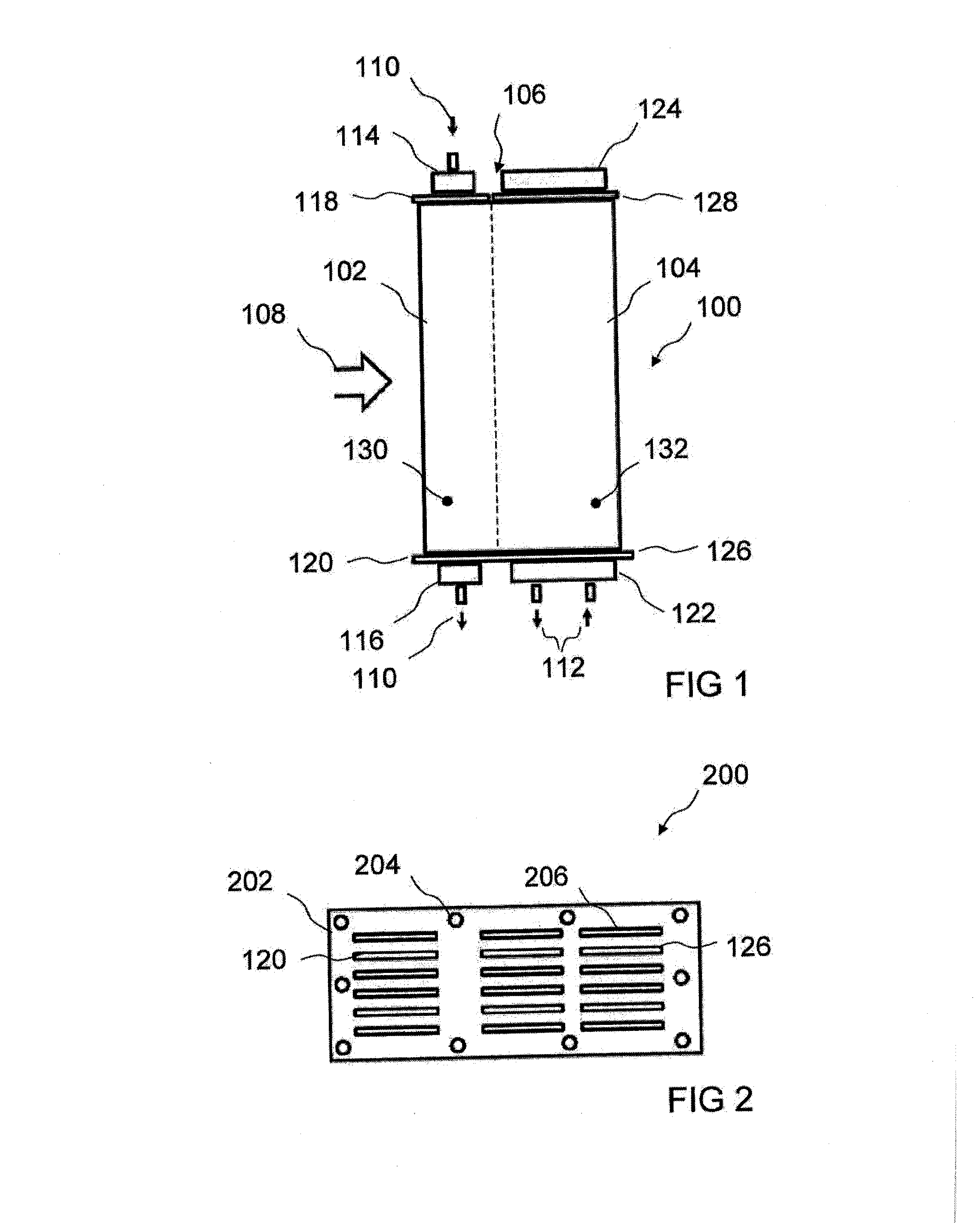
[0037]FIG. 1 shows an illustration of a heat exchanger 100 according to an exemplary embodiment of the present invention. Heat exchanger 100 has a preliminary stage 102 and a main stage 104. Preliminary stage 102 and main stage 104 are disposed within a single structural part and connected by means of a compensating component 106. Preliminary stage 102 is disposed transverse to a charge air stream 108 upstream of main stage 104. Charge air stream 108 has a high temperature before preliminary stage 102. The temperature is reduced in preliminary stage 102 in that thermal energy is transferred from charge air stream 108 to a first coolant stream 110, here, for example, a high-temperature coolant stream, by pr...


PUM


Abstract

A heat exchanger for cooling of charge air for an internal combustion engine of a motor vehicle is provided. The heat exchanger has a preliminary stage, a main stage, and a compensating component. The preliminary stage has at least one preliminary stage fixed bearing base and a preliminary stage floating bearing base. The main stage has at least one main stage fixed bearing base and a main stage floating bearing base. In a heat transfer region of the main stage, at least one main stage channel for a main stage coolant is disposed. The compensating component is configured to compensate a position difference between corresponding components of the preliminary stage and the main stage, whereby the position difference is based on a thermally induced elongation difference between the at least one preliminary stage channel and the at least one main stage channel.

Description

[0001]This nonprovisional application claims priority under 35 U.S.C. §119(a) to German Patent Application No. DE 10 2011 082 797.8, which was filed in Germany on Sep. 15, 2011, and which is herein incorporated by reference.BACKGROUND OF THE INVENTION[0002]1. Field of the Invention[0003]The present invention relates to a heat exchanger for cooling charge air for an internal combustion engine of a motor vehicle.[0004]2. Description of the Background Art[0005]In conventional charge air cooling in a motor vehicle, the charge air is compressed, for example, by means of an exhaust turbocharger or compressor and cooled after the compression in a charge air cooler to increase the charge air density. The charge air cooler can be made as a direct charge air cooler with a direct heat transfer between the ambient air and charge air. Likewise, the charge air cooler can be made as an indirect charge air cooler with heat transfer from the charge air to a coolant with a high heat capacity, for exa...

Claims


Application Information

Patent Timeline
IPC IPC(8): F02B29/04F28F7/00
CPCY02T10/146F02B29/0412F02B29/0462F28F2265/26F28F9/0241F28D7/0091F28F9/02Y02T10/12
Inventor EILEMANN, ANDREASFEHRENBACH, MATTHIASKOELBIN, RUEDIGEREHRMANNTRAUT, JOHANN
Owner MAHLE INT GMBH
Why Eureka
Try Eureka