Waste heat utilizing device for air compressor

a technology of air compressor and heat utilization device, which is applied in the direction of lighting and heating apparatus, refrigeration machines, steam engine plants, etc., can solve the problems of affecting the efficiency of heat recovery, and occupying a large proportion of the entire power consumption of the factory, so as to achieve the elimination of the need for a separate cooling device, efficient recovery, and power recovery

Active Publication Date: 2013-03-21
ANEST IWATA CORP
View PDF10 Cites 13 Cited by
  • Summary
  • Abstract
  • Description
  • Claims
  • Application Information

AI Technical Summary

Benefits of technology

[0017]Preferably in the device of the present invention, constituent devices are housed in a single housing, the housing is provided with an outside air introduction port and an outside air discharge port, the condenser includes an outside air flow forming device and a heat exchanger that cools the low boiling point medium using an outside air flow, and outside air is introduced through the outside air introduction port by the outside air flow forming device, whereby the outside air flow forming device forms an outside air flow that passes through the heat exchanger inside the housing so as to cool the low boiling point medium and is then discharged from the outside air discharge port. The outside air flow forming device is an air blower, a fan, or the like, for example, which is capable of cooling the low boiling point medium in the condenser using the outside air flow formed in the housing and also cooling and ventilating the constituent devices, including the air compressor. As a result, the need to provide a separate cooling device is eliminated.
[0018]According to the device of the present invention, the condenser interposed on the discharge path and the low boiling point medium circulation path of the air compressor performs heat exchange between the low boiling point medium and the compressed air discharged from the air compressor or the lubricating oil included in the compressed air such that the low boiling point medium evaporates, whereupon the evaporated low boiling point medium is introduced into the expansion machine so as to operate the expansion machine. As a result, the potential heat of the compressed air discharged from the air compressor can be recovered efficiently as power for operating the expansion machine, and this recovered power enables a reduction in the power consumption of the air compressor.

Problems solved by technology

An air compressor is one of the machines that consume the greatest amounts of power in a typical factory, and therefore takes up a large proportion of the entire power consumption of the factory.
As a result, a heat recovery rate deteriorates.

Method used


Image

  • Waste heat utilizing device for air compressor
  • Waste heat utilizing device for air compressor
  • Waste heat utilizing device for air compressor

Examples


first embodiment

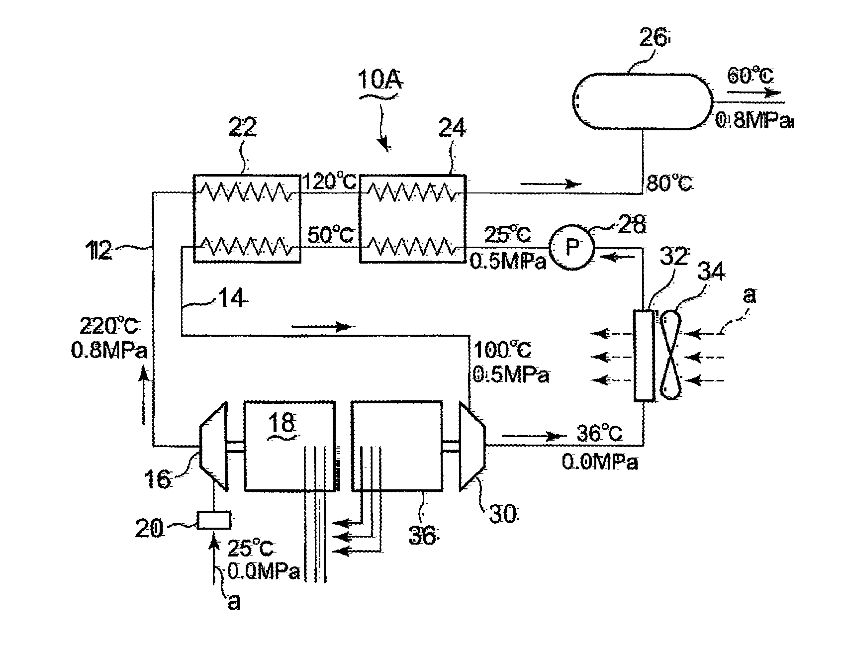
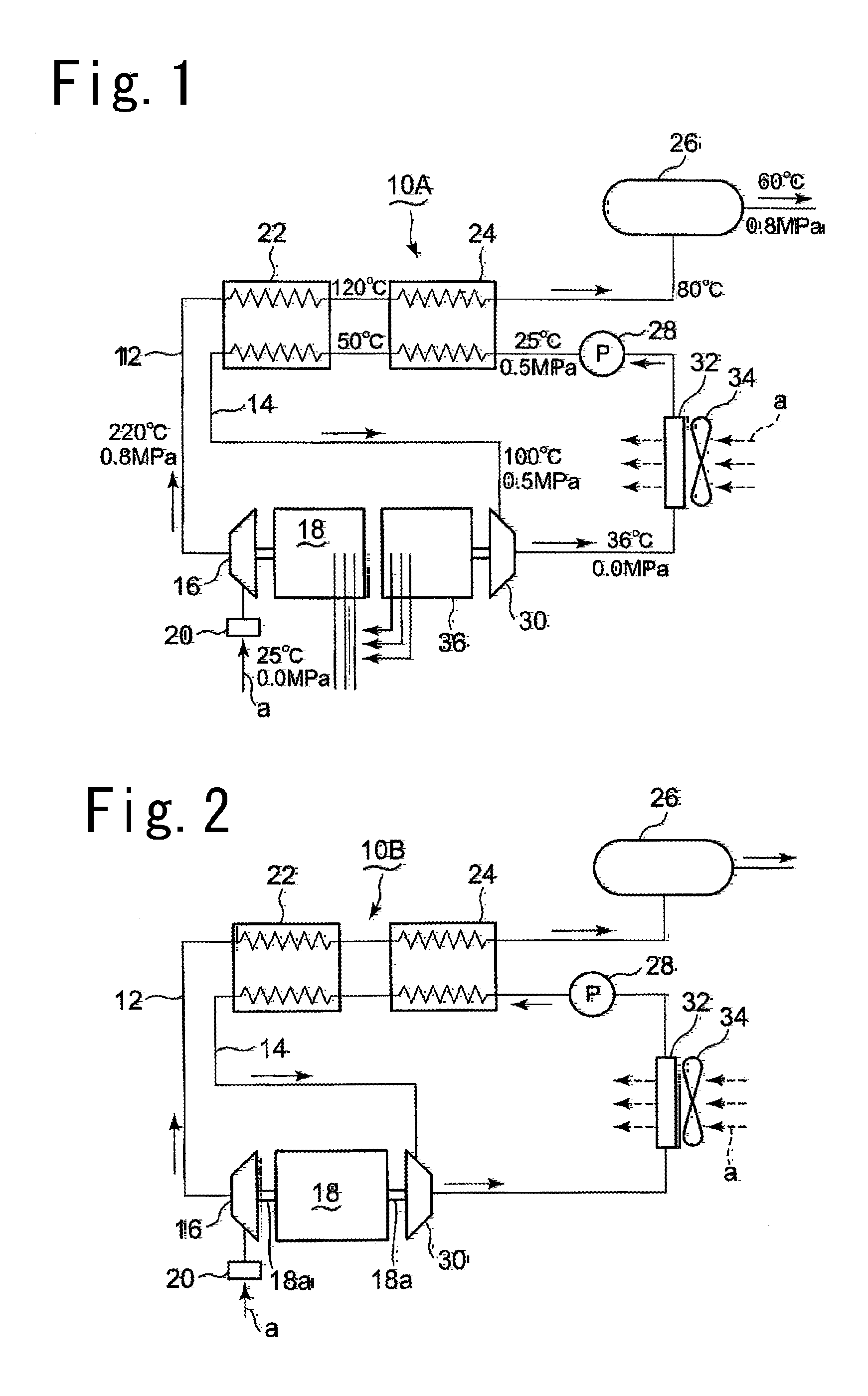
[0027]A first embodiment in which the device of the present invention is applied to an oil free air compressor will be described below using FIG. 1. A waste heat utilization device 10A according to the embodiment shown in FIG. 1 is constituted by a discharge path 12 of the compressor, a low boiling point medium circulation path 14, and devices interposed on these paths. An oil free air compressor 16 is driven by a drive motor 18, and when the oil free air compressor 16 is driven, outside air a is suctioned through an air filter 20. Compressed air discharged from the oil free air compressor 16 is held temporarily in an air receiver 26 after passing through an evaporator 22 and a preheater 24, and is then supplied to a required destination.

[0028]The circulation path 14, meanwhile, is connected to the evaporator 22 and the preheater 24, and a circulation pump 28, a scroll type expansion machine 30, and a condenser 32 are interposed thereon. The low boiling point medium is circulated al...

second embodiment

[0033]Next, a second embodiment of the device of the present invention will be described using FIG. 2. In a waste heat utilization device 10B according to this embodiment, the oil free air compressor 16 and the scroll type expansion machine 30 are connected to a single output shaft 18a of the drive motor 18. All other configurations are identical to the first embodiment. In this embodiment, a rotary torque of the oil free air compressor 16 can be reduced by rotating the scroll type expansion machine 30 using the low boiling point medium.

[0034]According to this embodiment, the power consumption of the oil free air compressor 16 can be reduced by reducing the rotary torque of the oil free air compressor 16. Further, using the oil free air compressor 16, the amount of evaporation occurring in the low boiling point medium can be increased, enabling an increase in the rotation speed of the scroll type expansion machine 30, and therefore an amount by which the rotary torque of the oil fre...

third embodiment

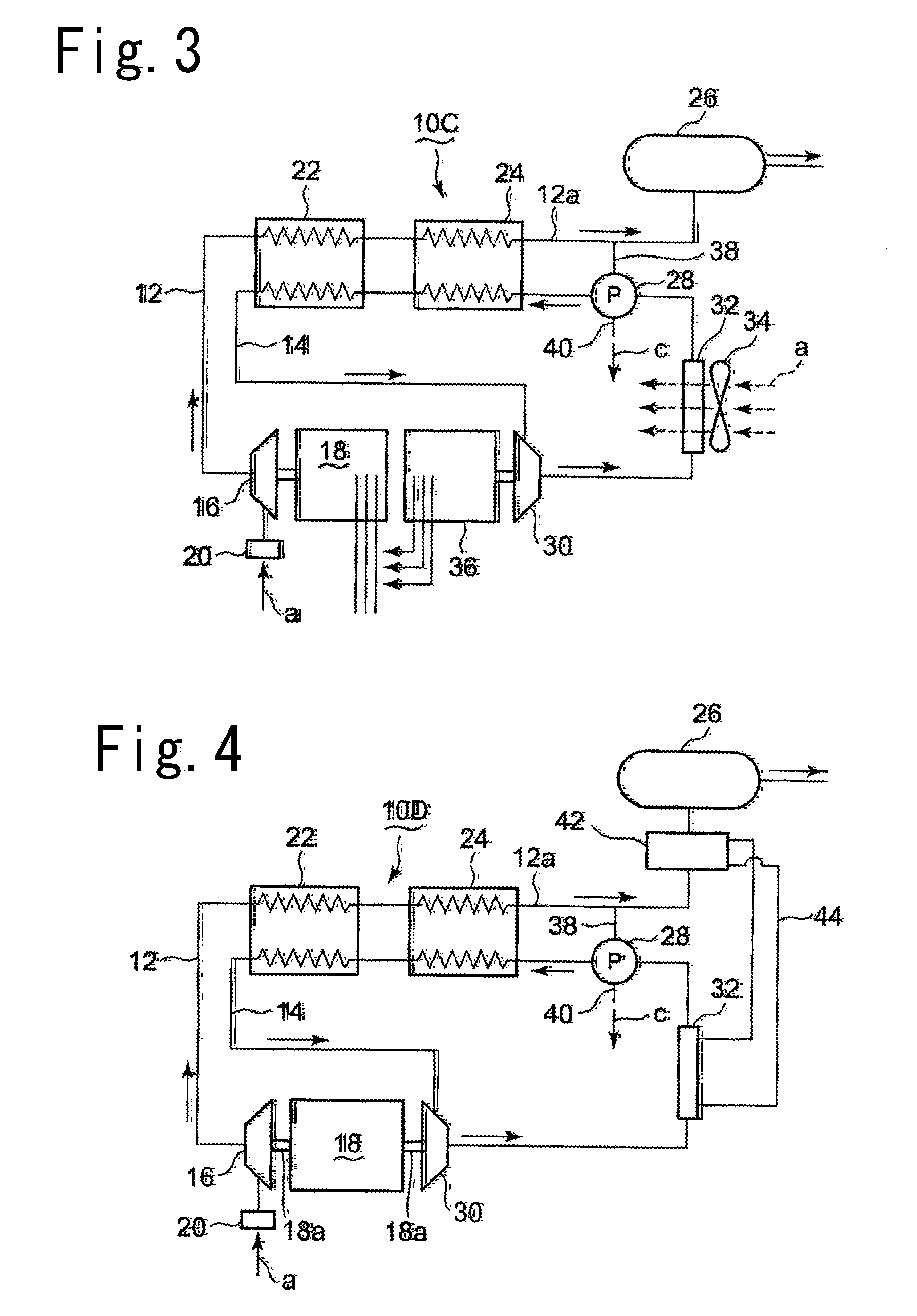
[0035]Next, a third embodiment of the device of the present invention will be described using FIG. 3. In a waste heat utilization device 10C according to this embodiment, a branch passage 38 is provided on a discharge path 12a on a downstream side of the preheater 24, and the branch passage 38 is connected to the circulation pump 28. A part of the compressed air is introduced into the circulation pump 28 from the branch passage 38 and used as driving force for the circulation pump 28. Used compressed air c is then discharged through a discharge passage 40 provided in the circulation pump 28. All other configurations are identical to the first embodiment.

[0036]According to this embodiment, a part of the compressed air is introduced into the circulation pump 28 and used as driving force for the circulation pump 28, and therefore power for driving the circulation pump 28 is not required.


PUM


Abstract

A waste heat utilization device for an air compressor includes: a discharge path of an oil free air compressor; a circulation path along which a low boiling point medium circulates; an evaporator provided on the circulation path to heat and evaporate the low boiling point medium using the potential heat of the compressed air; and a preheater provided on an upstream side of the evaporator to preheat the low boiling point medium using the potential heat of the compressed air. A scroll type expansion machine is rotated by the low boiling point medium evaporated by the evaporator and increased in pressure, and power is generated by a power generator connected to a rotary shaft of the scroll type expansion machine. The low boiling point medium discharged from the scroll type expansion machine is then cooled and condensed by a condenser.

Description

BACKGROUND OF THE INVENTION[0001]1. Field of the Invention[0002]The present invention relates to a waste heat utilization device for an air compressor that effectively utilizes potential heat of compressed air discharged from the air compressor in order to reduce a power consumption of the air compressor.[0003]2. Description of the Related Art[0004]Compressed air discharged from an air compressor reaches high temperatures of up to 200° C., for example, and therefore, as disclosed in Japanese Patent Application Publication No. 2010-101184, the compressed air is cooled by an aftercooler using cooling water and then cooled further by a refrigeration type dryer using a coolant, whereupon moisture contained in the compressed air is condensed and separated for use. An air compressor main body is thus prevented from overheating by water cooling, air cooling, or the like. An air compressor is one of the machines that consume the greatest amounts of power in a typical factory, and therefore ...

Claims


Application Information

Patent Timeline
Patent Type & Authority Applications(United States)
IPC IPC(8): F25B9/06
CPCF25B9/06F01K25/08
Inventor FUJIOKA, TAMOTSUUNAMI, ATSUSHI
Owner ANEST IWATA CORP
Why Eureka
Try Eureka