Spinal assembly load gauge

a technology of spinal assembly and load gauge, which is applied in the field of spinal assembly load gauge, can solve the problems of no bone screw assembly that solved both degenerative and deformity problems, and achieve the effects of reducing spinal implants, improving the control of spinal correction forces, and reducing implant-vertebral load

Inactive Publication Date: 2013-03-21
SIMONSON PETER MELOTT
View PDF32 Cites 30 Cited by
  • Summary
  • Abstract
  • Description
  • Claims
  • Application Information

AI Technical Summary

Benefits of technology

[0010]The present invention is a spinal fixation assembly that includes a load gauge to measure the force that must be applied to properly position the spinal fixation assembly vis-à-vis spinal vertebrae. In the preferred embodiment, the load gauge can include a mechanical spring or an electrical load cell. Preferably, the load gauge is located within a bone screwdriver and / or reduction crimp where force magnitude changes occur when translating or reducing spinal implants. Since the correction of spinal deformities usually involves higher implant-vertebra load with possible bone-screw interface damage, implant pullout or vertebral fracture, the present invention allows surgeons to have better control over such correction forces and more flexibility on how and how much the deformed spine is corrected.
[0011]The present invention makes it possible for spinal translation to be performed in a more incremental and less risky way by applying appropriate forces on each implant and locking them at any point between partial and complete translations. A real time measurement of these implant, inter-vertebral and spinal segment forces allows for a smoother and safer vertebral alignment during reduction or translation.

Problems solved by technology

For a long time, however, there was no bone screw assembly that solved both degenerative and deformity problems.

Method used


Image

  • Spinal assembly load gauge
  • Spinal assembly load gauge
  • Spinal assembly load gauge

Examples


Embodiment Construction

I. GENERAL DESCRIPTION

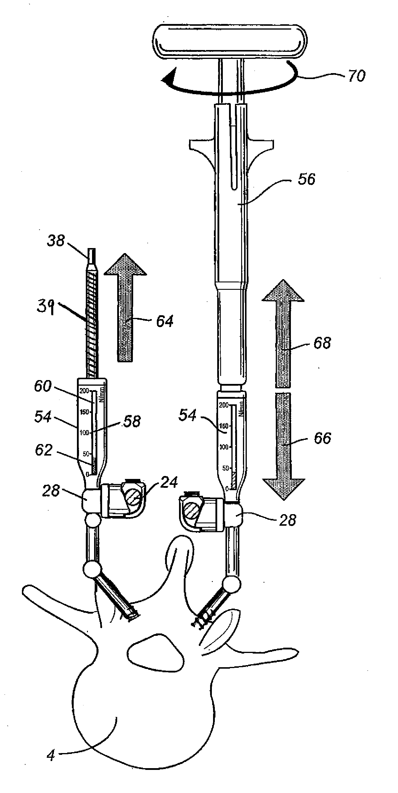
[0028]One embodiment of the present invention is illustrated FIG. 6. It is a load gauge 58 placed onto or inside an instrument used with a bone screw assembly. In a preferred embodiment, a reduction crimp 54 with a load gauge 58 threaded at its distal or top end is placed over a threaded 39 long post 38. The lower or smaller end of reduction crimp 54 engages and locks onto a bone screw connector 28. A commercially available reduction crimp called a Provisional Reduction Crimp (Product #8361963) sold by Medtronic Sofamor Danek Inc. is similar to the reduction crimp 54 shown in FIG. 6. In this embodiment, the mechanical, analog or digital components of the load gauge 58 are placed inside the body of the reduction crimp 54 or its driver 56. Furthermore, a visible and graduated Newton / mm scale 60 may be positioned on the surface of the reduction crimp 54. The load gauge 58 may also include a bar-type indicator 62. Such an indicator 62 may preferably have a variety ...


PUM


Abstract

A load gauge to measure the forces that must be applied to properly position a spinal fixation assembly to one or more vertebrae. In a preferred embodiment, said load gauge is attached to a bone screw. The bone screw is in turn connected to a rod through a connector. After the bone screw is inserted into a vertebrae, the load gauge measures the force that must be applied to properly position the spinal fixation assembly vis-a-vis the vertebrae. The present invention allows surgeons to have more flexibility on how and how much the deformed spine is corrected.

Description

CROSS-REFERENCE TO RELATED APPLICATIONS[0001]This application claims priority to U.S. Provisional Application No. 61 / 536,487, filed on Sep. 19, 2011, the disclosure of which is incorporated herein by reference in its entirety for all purposes.FIELD OF THE INVENTION[0002]The present invention relates to orthopedics and spinal surgery, more particularly to an instrument that measures the load forces on spinal implants and, especially, bone screws.BACKGROUND OF THE INVENTION[0003]Several techniques and systems have been developed for correcting and stabilizing the spine and facilitating a common spinal surgical procedure called fusion. The most widely used systems use a bendable rod that is placed longitudinally along the length of the spine. Such a rod is typically bent to follow the normal curvature of the spine. In such a procedure, a rod is attached to various vertebrae along the length of the spinal column by a number of bone screws inserted into the vertebral body, and, in some c...

Claims


Application Information

Patent Timeline
Patent Type & Authority Applications(United States)
IPC IPC(8): A61B17/70A61B17/88
CPCA61B17/7077A61B2019/464A61B17/7083A61B2090/064
Inventor SIMONSON, PETER MELOTT
Owner SIMONSON PETER MELOTT
Why Eureka
Try Eureka