Fuel injection rate shaping in an internal combustion engine

a technology of fuel injection rate and internal combustion engine, which is applied in the direction of liquid fuel feeders, machines/engines, electric control, etc., can solve the problems of introducing computational errors, requiring an abnormal number of computation cells, and not being able to model numerically on the computer the fuel spray and combustion phenomena, etc., and achieve the effect of reducing fuel consumption

Inactive Publication Date: 2013-03-28
CENT RICERCHE FIAT SCPA
View PDF17 Cites 10 Cited by
  • Summary
  • Abstract
  • Description
  • Claims
  • Application Information

AI Technical Summary

Benefits of technology

[0014]The aim of the present invention is hence to provide specific modes of use of fuel injection rate shaping in which the main fuel injection starts exactly when the pilot fuel injection terminat

Problems solved by technology

This experimental campaign has become necessary in so far as the results that the Applicant needed to obtain could not be obtained via computer simulations, since the mathematical models of fuel injection and combustion today available do not guarantee the necessary degree of reliability and accuracy.
In fact, up to now it has not been possible to model numerically on the computer the fuel spray and combustion phenomena because the ratio between the minimum size of a fuel microdrop (diameter=1 μm) and the size of a combustion chamber (diameter=100 mm) is too small and would require an abnormal number of computation cel

Method used


Image

  • Fuel injection rate shaping in an internal combustion engine
  • Fuel injection rate shaping in an internal combustion engine
  • Fuel injection rate shaping in an internal combustion engine

Examples


Embodiment Construction

[0018]The present invention will now be described in detail with reference to the attached figures for enabling a skilled person skilled to reproduce it and use it. Various modifications to the embodiments described will be immediately evident to the skilled person and the general principles described can be applied to other embodiments and applications without thereby departing from the sphere of protection of the present invention, as defined in the appended claims. Consequently, the present invention must not be considered as being limited to the embodiments described and illustrated, but it must be granted the widest sphere of protection in compliance with the principles and characteristics disclosed and claimed herein.

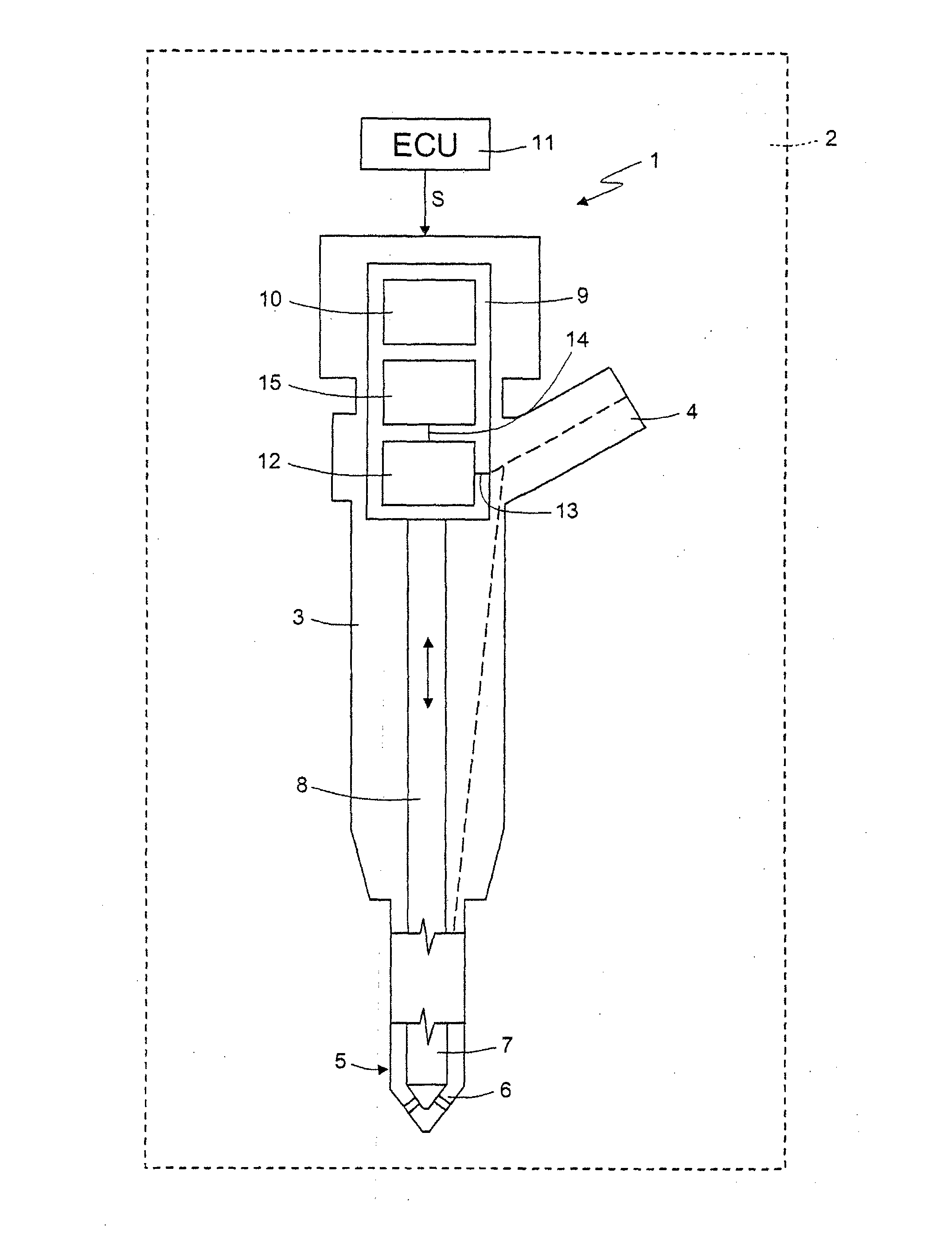
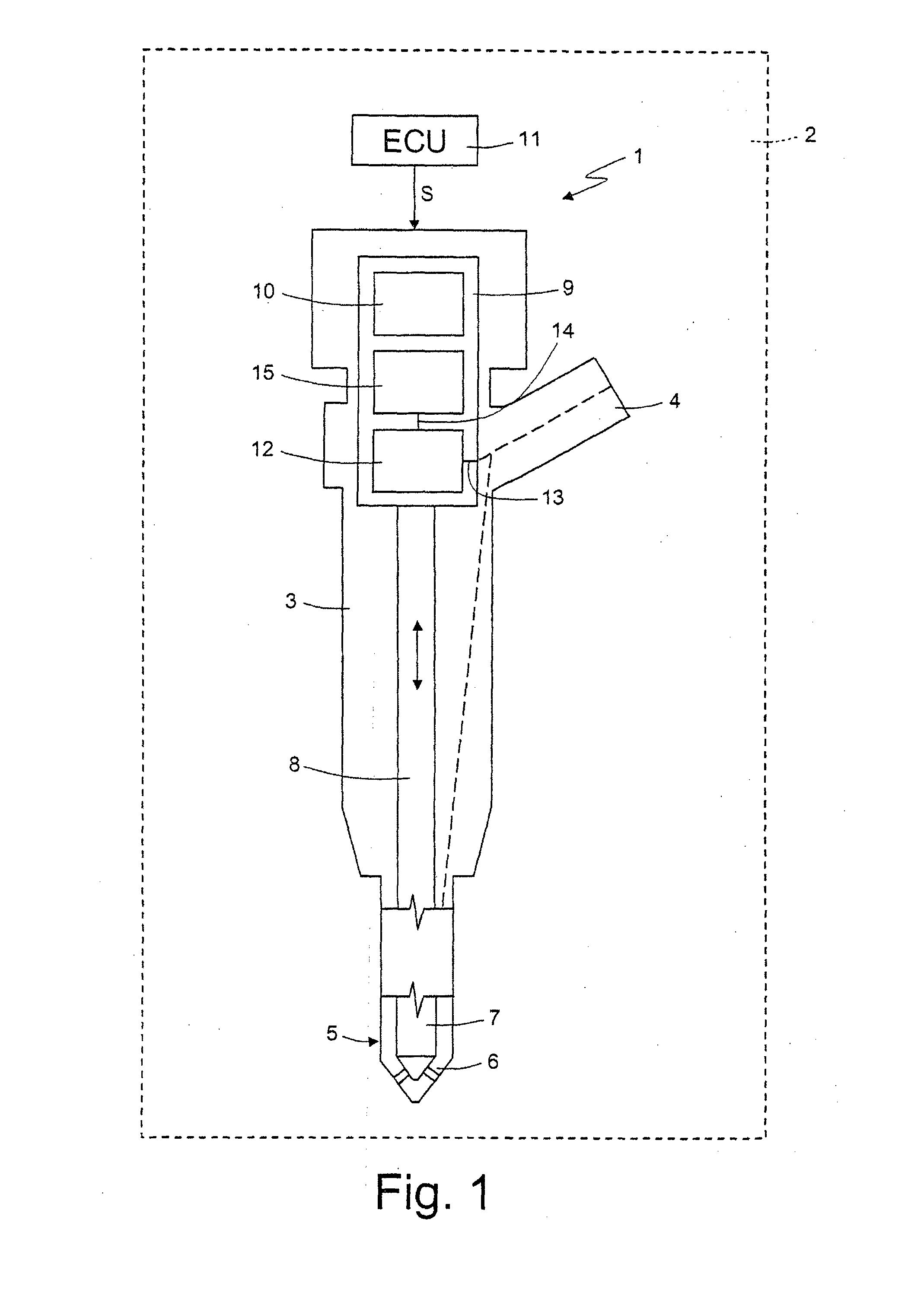
[0019]FIG. 1 shows a fuel electroinjector, referenced as a whole by 1, for a high pressure fuel injection system 2, depicted schematically with a dashed line, in particular of the common rail type, for an internal combustion engine (not shown), in particular a die...


PUM


Abstract

A fuel injection system for an internal combustion engine, comprising at least one fuel electroinjector, and an electronic control unit configured to supply the fuel electroinjector, in a fuel injection phase in an engine cylinder, with at least a first electrical command to cause a first fuel injection to be carried out, and a second electrical command cause a second fuel injection temporally subsequent to the first fuel injection to be carried out, the first and second electrical commands being separated in time by an electrical dwell time such that the second fuel injection starts without any discontinuity in time with respect to the first fuel injection. The electronic control unit is further configured to cause the first and second fuel injections to be carried out in engine operating conditions characterized by reduced fuel ignition delays, wherein fuel combustion is prevalently diffusive and heat released during fuel combustion is sensitive to fuel injection law.

Description

TECHNICAL FIELD OF THE INVENTION[0001]The present invention relates to fuel injection rate shaping (IRS) in an internal combustion engine, in particular of the type provided with a common rail fuel injection system.STATE OF THE ART[0002]As is known, in latest generation common rail fuel injection systems, the electroinjectors are controlled electronically by an electronic control unit appropriately programmed to supply the electroinjectors with electrical commands such as to provide fuel injection strategies specifically designed to achieve given targets in terms of fuel consumption or levels of emission of pollutant substances.[0003]For example, EP 1,035,314 B1 in the name of the Applicant discloses a common rail fuel injection system in which the electronic control unit is programmed to cause the fuel injection system to carry out, in one and the same engine cylinder and in one and the same engine cycle, multiple temporally consecutive fuel injections comprising:[0004]a main fuel ...

Claims


Application Information

Patent Timeline
IPC IPC(8): F02D41/34F02M41/00
CPCF02D41/20F02D41/3017F02D41/3827F02M41/00F02M47/027Y02T10/44F02D41/345F02D41/403Y02T10/40
Inventor CASALONE, MARCOTONETTI, MARCO
Owner CENT RICERCHE FIAT SCPA
Why Eureka
Try Eureka