AI technical title is built by PatSnap AI team. It summarizes the technical point description of the patent document.
a solar panel and high-yield technology, applied in the field of thermal solar panels, can solve the problems of limited thermal performance of such a solar panel and low performance of solar panels at high temperatures, and achieve the effect of satisfying performan
Inactive Publication Date: 2013-03-28
HELIOPROCESS
View PDF0 Cites 10 Cited by
Summary
Abstract
Description
Claims
Application Information
AI Technical Summary
This helps you quickly interpret patents by identifying the three key elements:
Problems solved by technology
Method used
Benefits of technology
Benefits of technology
The present invention is about a thermal solar panel that works well even at high temperatures. It achieves this by minimizing heat loss and maximizing thermal performance. The use of mirrors instead of lenses for focusing the thermal radiation helps to avoid the problem of achromatic effects and makes the device simpler and more efficient. The heat collecting element is designed to have low thermal emission and high heat absorption.
Problems solved by technology
The thermal performance of such a solar panel is generally limited by heat losses due to thermal radiation emitted by the heat collecting element.
Thus, such a solar panel generally has low performance at high temperatures, e.g., at temperatures greater than 400° C.
Method used
Image
Click on the blue label to locate the original text in one second.
Reading with bidirectional positioning of images and text.
Examples
first embodiment
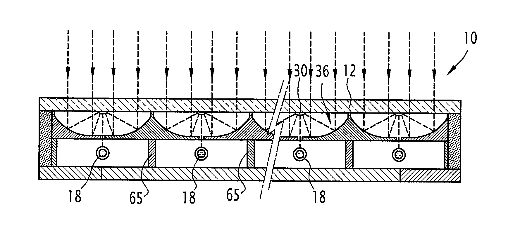
[0053]In accordance with first embodiment described, at least one wall, amongst the lower wall 22, the lateral walls 24, and the upper wall 26, has one such reflective area. Advantageously, each wall 22, 24, and 26 of the housing 20 has such a reflective area, and each of these reflective areas extends over the entire corresponding wall. Thus, almost the entirety of the thermal radiation emitted by the collector 18 is reflected by the walls 22, 24, and 26 of the housing 20, to be re-absorbed by the heat collecting element 18. The thermal losses due to thermal radiation emitted by the collector 18 are thus limited, and the thermal performance of the panel 10 is particularly high.
[0054]For example, each reflective area is formed by a reflective coating, e.g., an aluminiumcoating, applied to the corresponding wall 22, 24, 26.
[0055]It will be noted that the quality of the reflection by these reflective areas is preserved over time because the inside of the solar panel 10 is a vacuum; t...
second embodiment
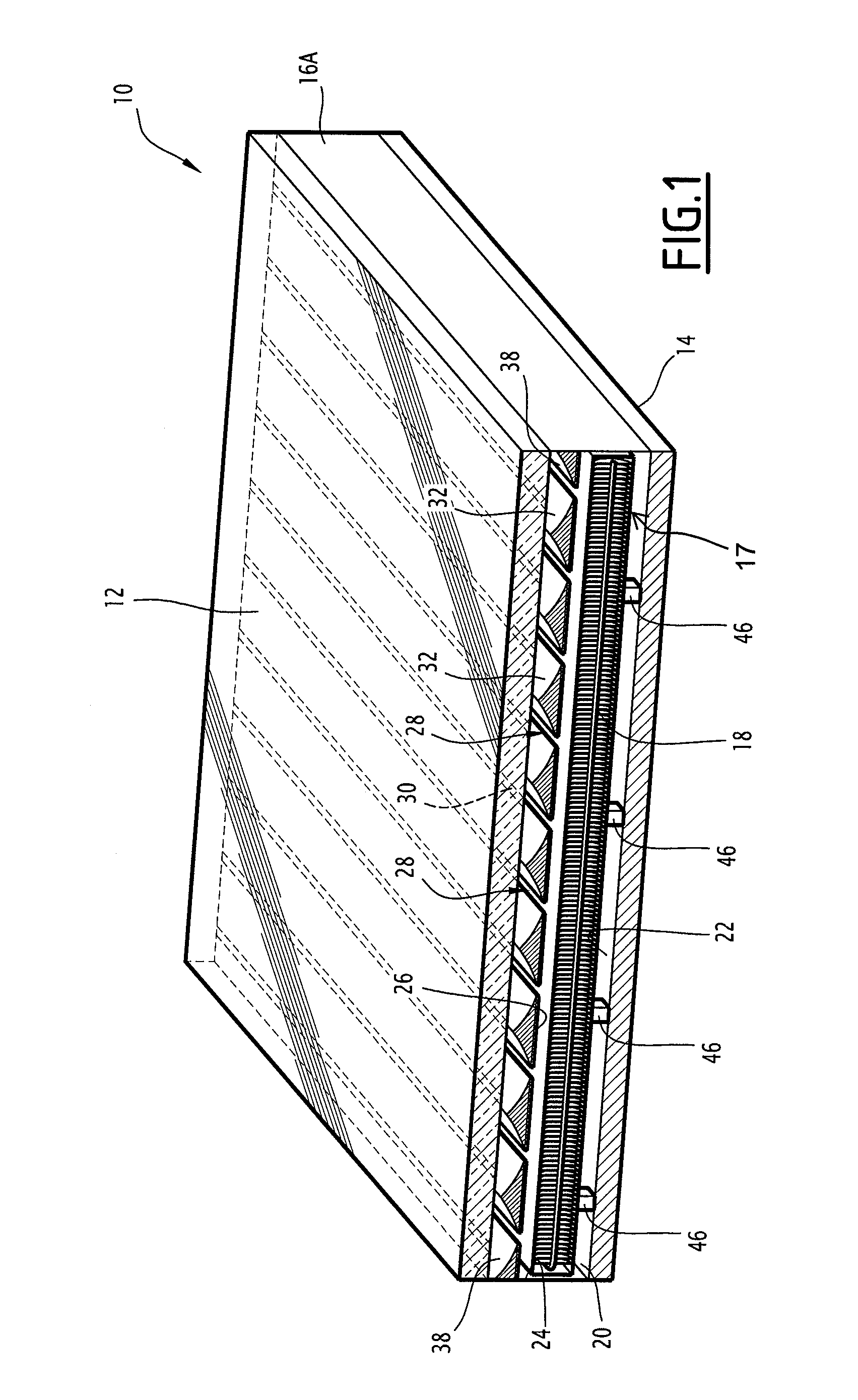
[0097]According to this second embodiment, the solar panel 10 includes several heat collecting elements 18, in particular a heat collecting element 18 by a group of primary 36 and secondary mirrors 30.
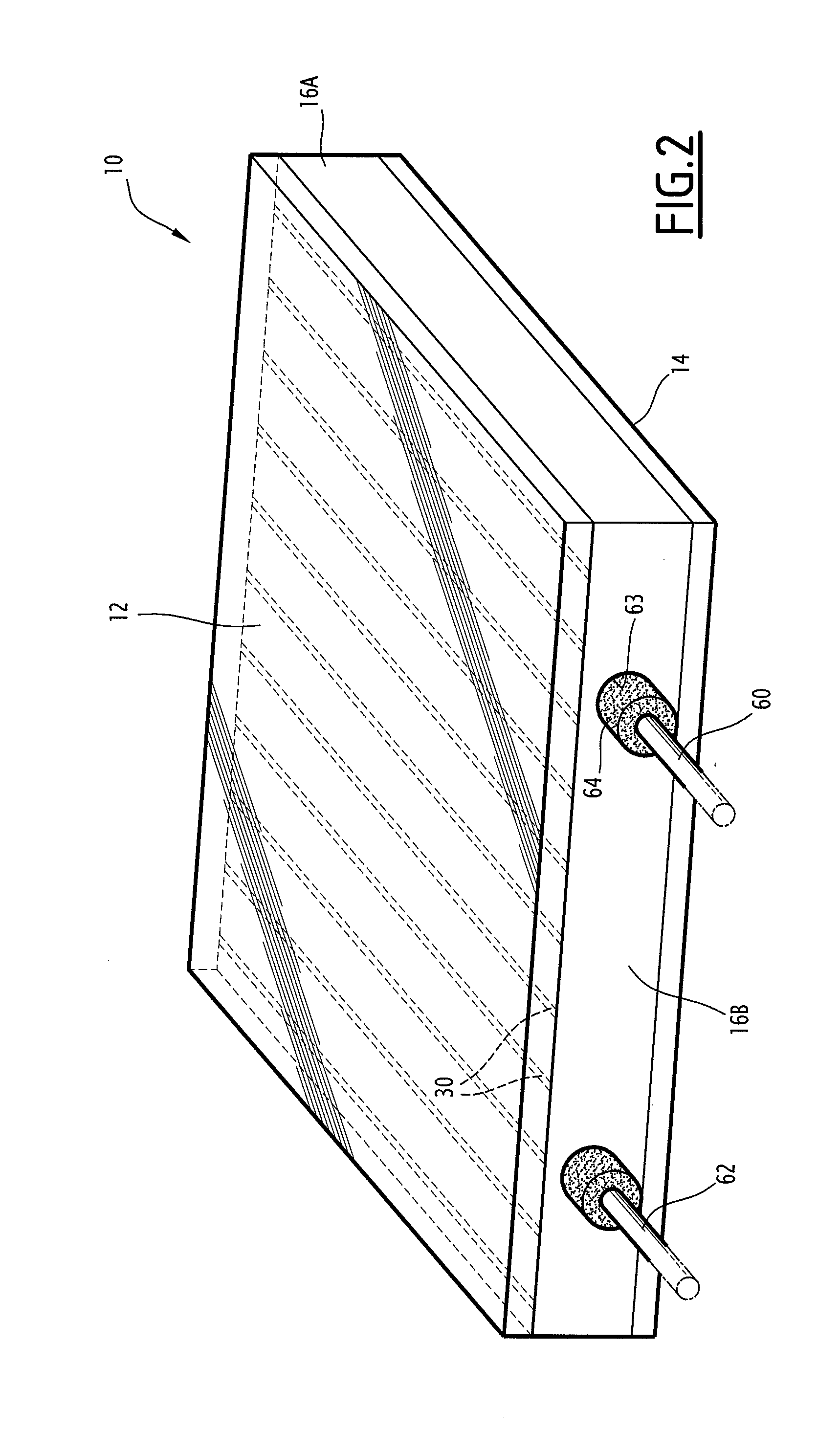
[0098]Each of these heat collecting elements 18 has a heat transfer function towards a heat storage element arranged, e.g., outside the thermal panel 10, which will be described below by reference to FIG. 10.
[0099]Preferably, the thermal solar panel 10 includes spacers 65, arranged between two adjacent heat collecting elements 18, and extending between the flat base 34 of a reflective element 32 and the lower face 14 of the panel 10, so as to delimit the respective housings for the heat collecting elements. Advantageously, these spacers 65 include a reflective coating.
[0100]An example of a heat collecting element 18 is shown in FIG. 8.
[0101]This heat collecting element 18 is formed by a tubular heat transfer element in which a coolant 66 circulates to ensure heat transfer. Preferably, ...
PUM
Abstract
The solar panel includes a housing for a heat collecting element, delimited by walls, one of which includes slits for the passage of solar rays. At least one reflective area is arranged to face the heat collecting element. At least one reflective strip is arranged outside the housing to face a respective slit so as to focus the solar rays received towards this slit. Elongated reflective elements are arranged side by side, and include coplanar flat bases, forming together the wall of the housing having slits and the flat base of at least one elongated reflective element forming a reflective area of this wall of the housing, and including one concave surface arranged to face the reflective strips such that the solar rays reflected by each concave surface are focused towards the corresponding reflective strip.
Description
[0001]This invention concerns a thermal solar panel intended for the storage and release of solar thermal energy.BACKGROUND[0002]A thermal solar panel of the type comprising at least one heat collecting element intended to receive solar rays is known from prior art. Such a solar panel is used, e.g., for coupling with a heat engine in order to transform solar heat energy into electrical or mechanical energy. In one variant, the solar heat energy may also be recovered in order to produce heat or cooling, e.g., for a heating or air-conditioning system.[0003]Normally, the heat collection element is generally tubular in shape, and is arranged in a glass vacuum tube, coaxially with the glass tube. The solar panel includes, inter alia, reflective elements so as to focus the solar rays received on the heat collecting element.[0004]The heat energy of the solar rays is then replaced by means of a coolant circulating in the core of the heat collecting element by means of heat transfer between ...
Claims
Application Information
Patent Timeline
Application Date:The date an application was filed.
Publication Date:The date a patent or application was officially published.
First Publication Date:The earliest publication date of a patent with the same application number.
Issue Date:Publication date of the patent grant document.
PCT Entry Date:The Entry date of PCT National Phase.
Estimated Expiry Date:The statutory expiry date of a patent right according to the Patent Law, and it is the longest term of protection that the patent right can achieve without the termination of the patent right due to other reasons(Term extension factor has been taken into account ).
Invalid Date:Actual expiry date is based on effective date or publication date of legal transaction data of invalid patent.
Patent Type & AuthorityApplications(United States)

