
Membrane touch keyboard structure for notebook computers

a notebook computer and keyboard technology, applied in the field of computer keyboards, can solve the problems of easy damage to the keys, affecting the use of the keyboard, and the structure of the keys, so as to reduce the thickness of the notebook computer, reduce the noise produced during use, and reduce the manufacturing time, labor and cost

Inactive Publication Date: 2013-03-28
KO & CAYMAN
View PDF3 Cites 60 Cited by
  • Summary
  • Abstract
  • Description
  • Claims
  • Application Information

AI Technical Summary

Benefits of technology

The present invention aims to improve the performance of notebook computers by integrating a membrane touch keyboard and a touch panel for controlling cursor movement. This allows for the use of touch keys on the keyboard, reducing noise and improving overall performance. The touch panel can also be manufactured simultaneously with the keyboard, reducing labor and cost while also making the computer thinner and more compact. This design complies with the modern trend for light, thin, short, and compact electronic products.

Problems solved by technology

The touch panels (for controlling the cursor movement), functional keys, keypad and hot keys of the notebook computer are manufactured separately, and then installed on to the notebook computer one by one, thus involving relatively more complicated manufacturing process and consuming more time and labor.
After being used for a long time, the structure of the press keys exerted with an external force will damage the keys easily.
As a result, the operating signal of the press key cannot be inputted.
In addition, each of the functional keys, keypad and hot keys of the keyboard of the notebook computer with the mechanical structure has a specific height, so that the keyboard installed on the notebook computer will have a certain thickness, so that the notebook computer cannot be carried by users easily and the conventional keyboard for notebook computers is incompliance with the light, thin, short and compact design of modern electronic products.

Method used


Image

  • Membrane touch keyboard structure for notebook computers
  • Membrane touch keyboard structure for notebook computers
  • Membrane touch keyboard structure for notebook computers

Examples


Embodiment Construction

[0049]The technical characteristics and contents of the present invention will become apparent with the following detailed description and related drawings. The drawings are provided for the purpose of illustrating the present invention only, but not intended for limiting the scope of the invention.

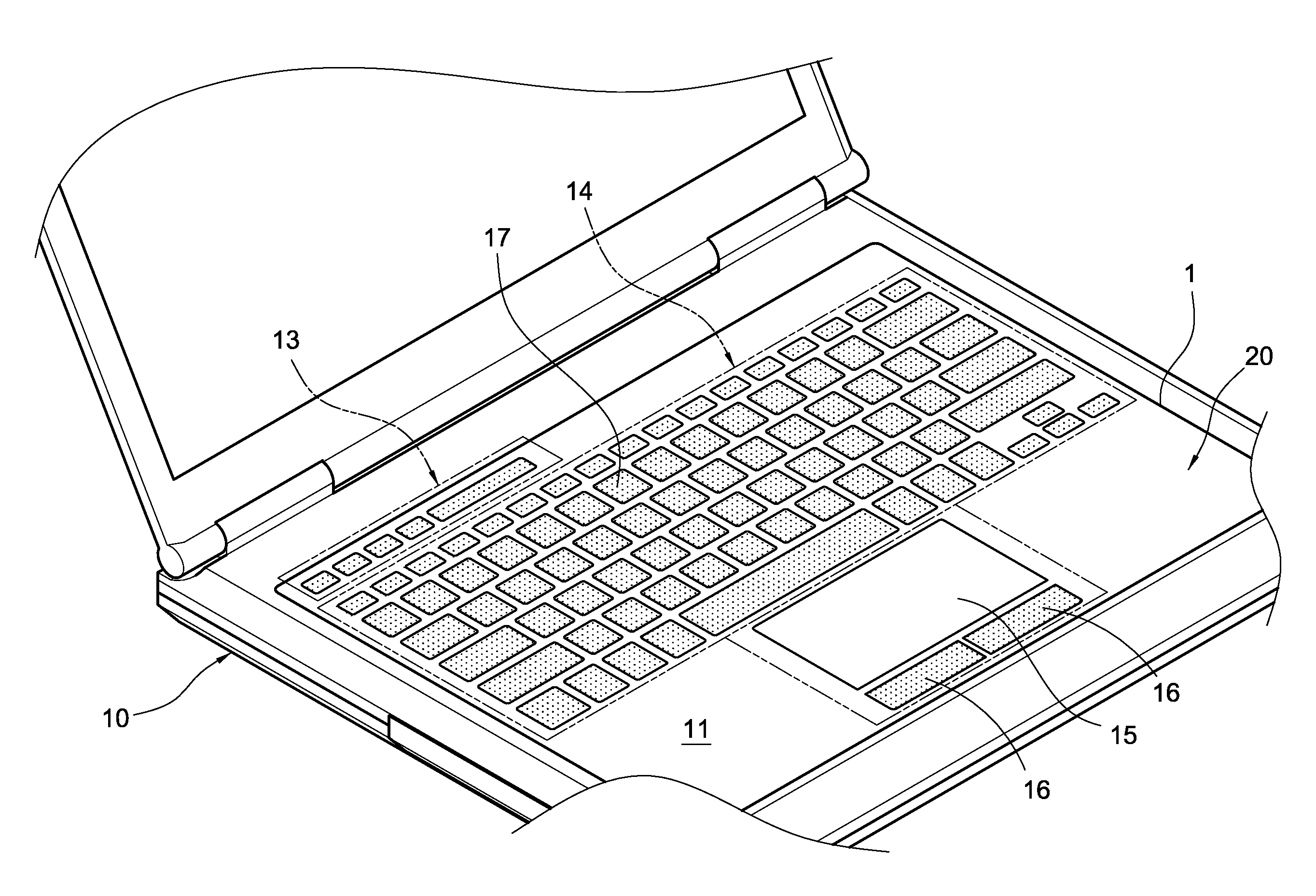
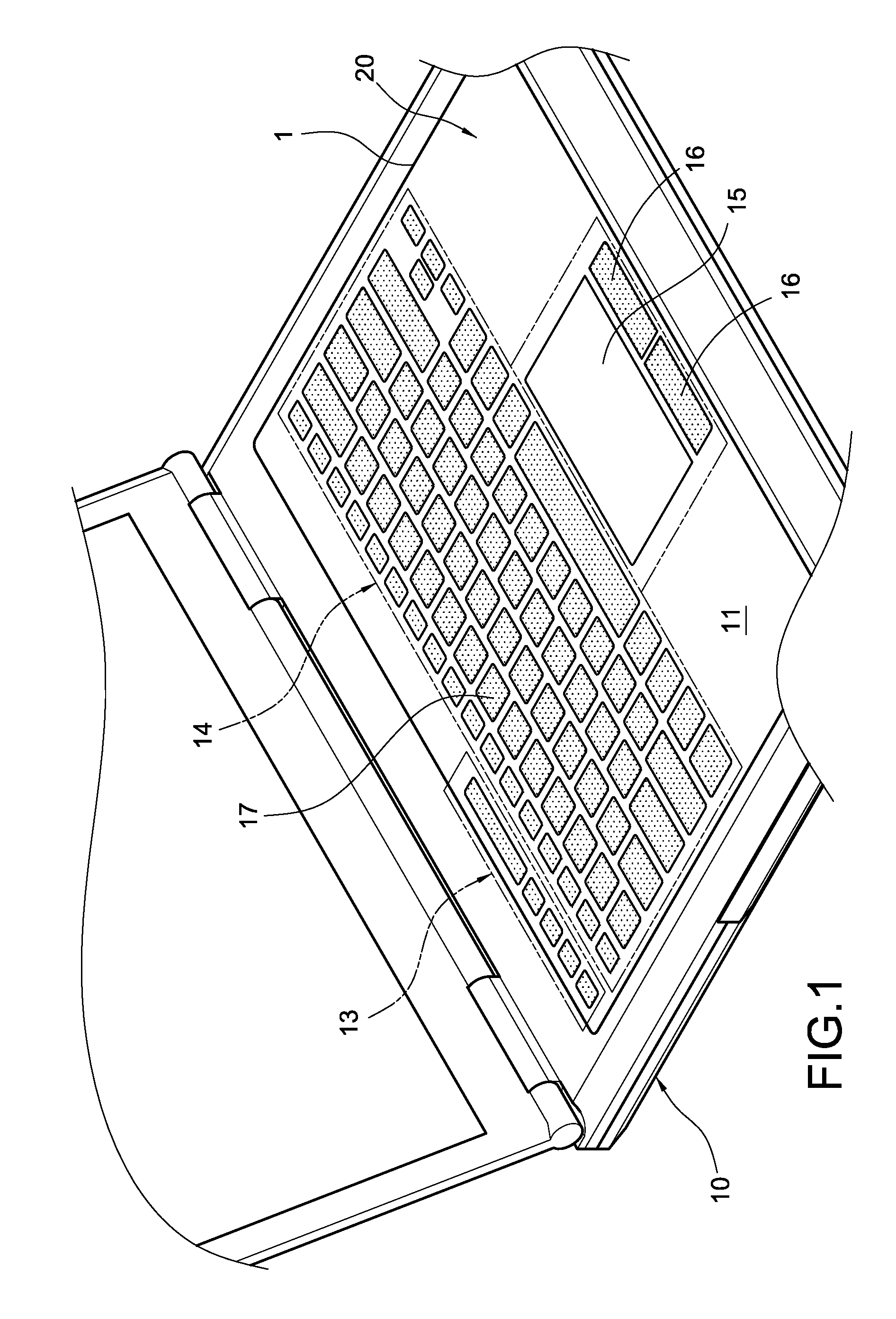
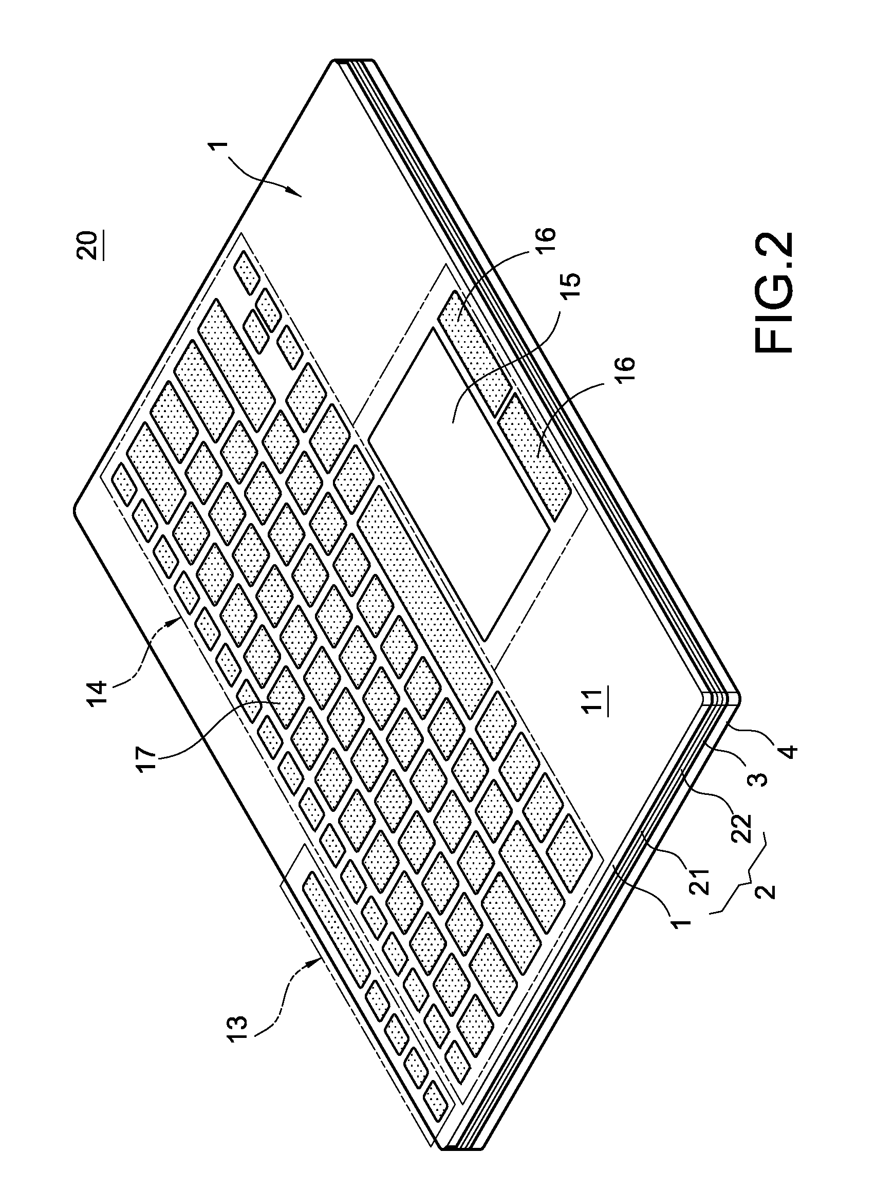
[0050]With reference to FIGS. 1 to 3 for the perspective view of a notebook computer, and the perspective view and exploded view of a membrane touch keyboard structure in accordance with the present invention, and FIGS. 4 and 5 for close-up view of a sensing layer as depicted in FIG. 3, and FIG. 6 for a close-up view of a backlight layer as depicted in FIG. 3 respectively, the notebook computer 10 includes a membrane touch keyboard 20, and the membrane touch keyboard 20 comprises: a panel 1, a sensing layer 2, a backlight layer 3 and a base layer 4.

[0051]The panel 1 is a transparent plastic sheet having a first surface 11 and a second surface 12, and the first surface 11 includes a plural...


PUM


Abstract

A membrane touch keyboard structure for notebook computers comprises a panel, a sensing layer, a backlight layer and a base layer. The panel includes hot key patterns, a key group pattern, a cursor control pattern, and a sensing key pattern. A first sensing block, first electrode blocks, a second sensing block, a third electrode block or a third sensing block, and a fourth sensing block correspond to sensing layers of the hot key patterns, key group pattern, cursor control pattern, and sensing key pattern. The sensing layers are resistive / capacitive films. The membrane touch keyboard and the touch panel are integrated to reduce the thickness of the notebook computer. When any hot key pattern, key group pattern, cursor control pattern or sensing key pattern is touched, the touch is sensed by the sensing layer to generate and output a sensing control signal to the notebook computer for an operation.

Description

FIELD OF THE INVENTION[0001]The present invention relates to a computer keyboard, in particular to a membrane touch keyboard structure for notebook computers.BACKGROUND OF THE INVENTION[0002]Keyboard is one of the necessary peripherals of desktop or notebook computers provided for users to input an operation instruction to execute a specific function.[0003]Besides a touch panel (for controlling a cursor movement), present existing keyboard used for notebook computers usually comes with functional keys, a keypad and hot keys which are press keys with a mechanical structure. For example, each press key has a key cap, and after the key cap is pressed, the internal assembly of the key cap presses at a supporting frame and an elastic rubber layer, such that the elastic rubber layer presses a thin-film or rigid printed circuit board to generate a signal to be input into a host computer.[0004]The touch panels (for controlling the cursor movement), functional keys, keypad and hot keys of th...

Claims


Application Information

Patent Timeline
IPC IPC(8): G06F3/02
CPCG06F1/1662G06F2203/04809G06F3/0202G06F1/1666
Inventor LIN, YU-KAI
Owner KO & CAYMAN
Learn More