Lighting system having a multi-light source collimator and method of operating such

Active Publication Date: 2013-03-28
MUSCO
View PDF3 Cites 27 Cited by
  • Summary
  • Abstract
  • Description
  • Claims
  • Application Information

AI Technical Summary

Benefits of technology

The patent aims to create an LED-based luminaire that can be tailored for sports and other wide-area lighting applications. It also aims to make the luminaire more cost-effective and to balance heat management, droop, and other factors with light output. The designed luminaire can accommodate a plurality of LED modules, each with one or more optical devices in combination with an envisioned lens, which can adjust the aiming of the LED modules and produce a desired composite beam output pattern. The number, type, and input power of LEDs within each module, as well as the overall design of the luminaire, can be adjusted to achieve the desired light output level and efficacy. Overall, the patent aims to provide a versatility and flexibility for LED-based luminaire designs to suit various lighting applications.

Problems solved by technology

For example, while high wattage HID lamps produce a significant amount of light, the lamps themselves are large (e.g., over 300 mm long and over 200 mm in diameter) and often require large and complex optical devices to harness the light and direct it towards the target area; this adds cost and size to the luminaire.
Adding to the size of the luminaire often increases wind loading (i.e., drag) and weight; thus the elevating structure (e.g., pole) must be more substantial, which also adds to cost.
Even then, there are limits to how much the light emitted from a single source can be shaped to suit a target area.
For example, even with a host of optical devices, it is difficult for a single metal halide HID luminaire to adequately illuminate a bend in a road (e.g., as in a cloverleaf interchange) without spill (i.e., light that does not contribute to illumination of the target area and so is wasted).
Unfortunately, in the current state of the art lower wattage HID lamps suffer from reduced efficacy (e.g., around 80 lm / W).
Given that many sports and other wide-area lighting systems are operated for twenty years or more before lamp replacement, the increased control does not justify the increased cost of operating the lower wattage HID lamps over time.
That being said, the use of LEDs has not yet extended to sports and other wide-area lighting applications, at least in part, because simply swapping out one type of light source for another does not address the issue of heat management—a factor known to greatly impact the operating life and efficacy of LEDs—which, if not properly addressed, diminishes the benefits of using LEDs.
Another issue of great concern is “droop”—a phenomenon experienced by LEDs wherein efficacy sharply decreases as current increases.
Unfortunately, the tradeoff is a significant decrease in efficacy; in some cases, increasing current beyond several milliamps (mA) results in a drop so severe as to render LEDs less efficient at converting electricity into light than other commercially available light sources (e.g., fluorescents).
This is no easy task as it is estimated that an LED-based sports lighting system can cost several times as much (initially) as a standard HID-based sports lighting system; this is due, at least in part, to the sheer number of LEDs needed to approximate the light output of a single high wattage HID lamp.
The deficiency here is that because LEDs are still an emerging technology there is a limit to the light output that can be produced while maintaining an acceptable efficacy.
Further, there is a limit to the size of optic that can be made to fit LEDs and still be formed by cost-effective molding techniques.
The deficiency here is that there comes a point when increasing current produces diminishing returns; droop and temperature increases, thereby reducing operating life and efficacy.

Method used


Image

  • Lighting system having a multi-light source collimator and method of operating such
  • Lighting system having a multi-light source collimator and method of operating such
  • Lighting system having a multi-light source collimator and method of operating such

Examples


embodiment 1

[0032]B. Exemplary Method and Apparatus Embodiment 1

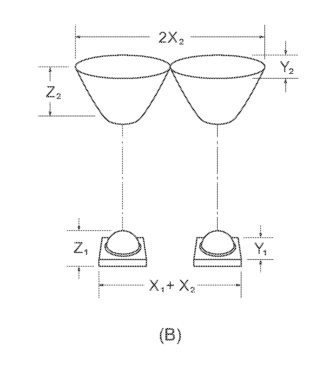
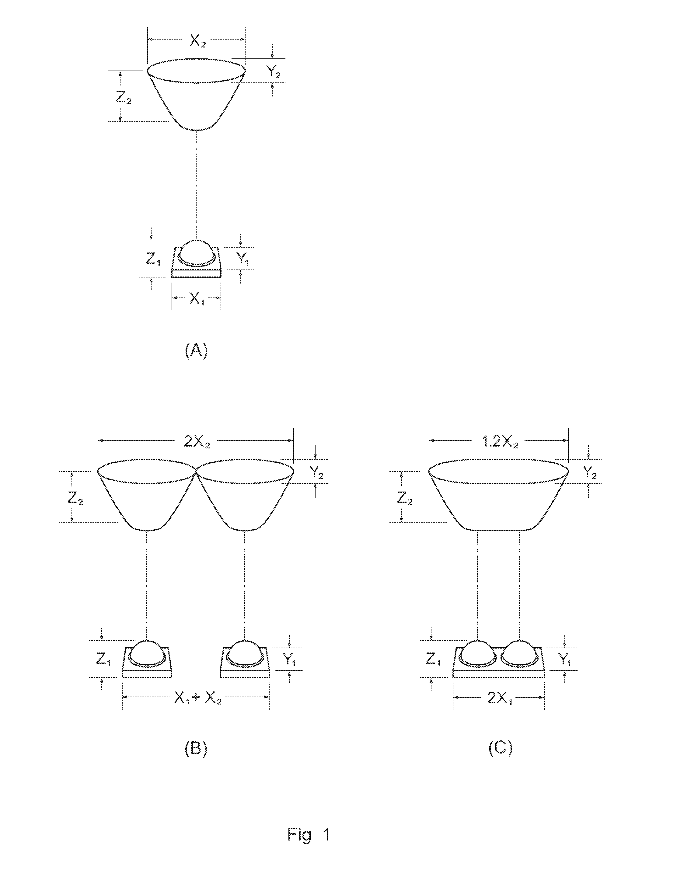
[0033]Envisioned is a luminaire employing a plurality of LEDs of sufficient type and in sufficient number so to approximate the light output of a traditional HID lamp used in wide-area lighting applications; an example of the latter is model 37405 quartz metal halide lamp available from GE Lighting Headquarters, Cleveland, Ohio, USA. According to aspects of the present invention, two or more LEDs are placed side-by-side to form a linear array, a single set of optical devices used for each linear array so to reduce the cost of the luminaire—or at least reduce the increase in cost of the luminaire. So for example, a linear array of two LEDs sharing a single lens, visor, and / or reflector essentially doubles the number of LEDs without doubling the number of optical devices; in essence, doubling the light output capacity without doubling the cost. This is contrary to conventional wisdom because it is known that multi-chip LEDs are comme...

embodiment 2

[0054]C. Exemplary Method and Apparatus Embodiment 2

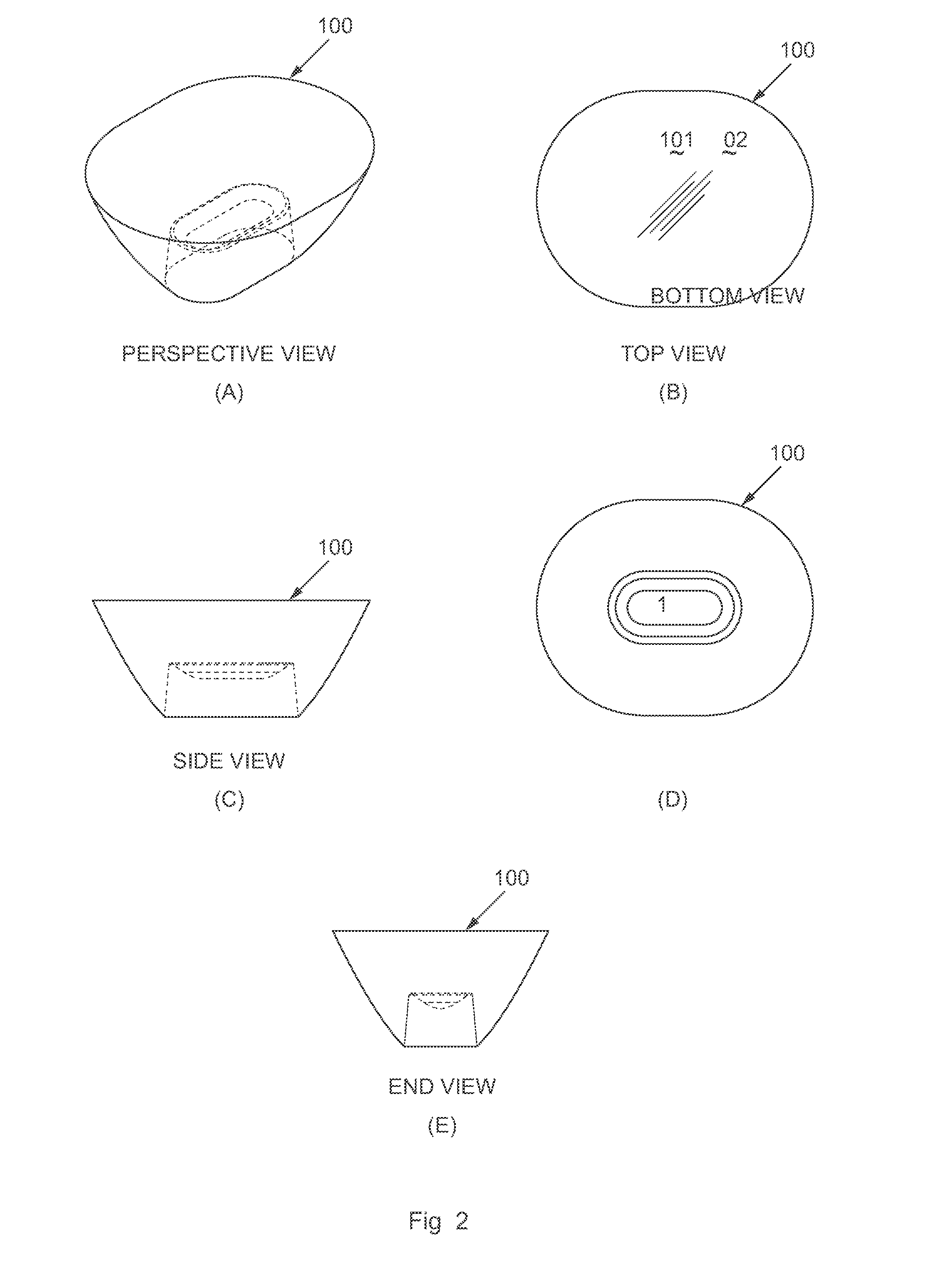
[0055]In some situations, a combination of factors could steer one away from a linear array of LEDs even if the corresponding beam output pattern is desirable. For example, one may find that to achieve a target efficacy for a given size of luminaire, a linear array of LEDs does not permit adequate packing of light sources in the available space. In some situations it may be preferable to produce a beam output pattern symmetric about all axes. In some situations it may be found that for a given model of LED, light losses are more readily attributed to droop than to increased temperature. In such a situation, to achieve a desired efficacy one may need to consider including more LEDs per lens so to diminish the effects of droop while accepting an increase in overall temperature. For whatever reason, it is not a departure from aspects according to the present invention to design a non-linear array for use with envisioned lens 100; this...


PUM

PropertyMeasurementUnit
Temperatureaaaaaaaaaa
Luminous fluxaaaaaaaaaa
Currentaaaaaaaaaa

Abstract

A lens is provided which is elongated along an axis so to accommodate a linear array of LEDs, the elongation of the lens resulting in a corresponding elongation of the beam output pattern; in practice, the axis of elongation may be oriented so to suit a target area or some portion thereof. A methodology is provided for use with said lens so to evaluate various factors such as droop, heat management, and light output for a given combination of light sources and luminaire design. Alternative designs of lens, as well as alternative optical devices, are also presented for use with said methodology.

Description

CROSS-REFERENCE TO RELATED APPLICATIONS[0001]This application claims priority under 35 U.S.C. §119 to provisional U.S. application Ser. No. 61 / 539,166, filed Sep. 26, 2011, hereby incorporated by reference in its entirety.I. BACKGROUND OF THE INVENTION[0002]In the current state of the art, sports and other wide-area lighting applications typically utilize high intensity discharge (HID) lamps; most often, high wattage (e.g., 1000 watt or more), installed in a luminaire elevated high above the target area, and accompanied by a variety of optical devices which help to shape the light projected therefrom. Some typical optical devices used in HID luminaires include reflectors, lenses, visors, or the like and are designed to reflect, collimate, block, or otherwise direct light so to produce the desired beam pattern at or near the target area. In many applications the term “target area” refers not only to the surface where a task is performed, but also a defined space above and / or about sa...

Claims


Application Information

Patent Timeline
IPC IPC(8): F21V15/01F21V7/00G01R31/28F21V5/04
CPCF21V5/001F21K9/90F21V7/22F21W2131/401Y10T29/49004F21W2131/407F21W2131/105F21V29/504F21K9/50F21W2131/406F21V5/04F21V29/507F21Y2105/10F21Y2115/10F21K2/00F21V15/01F21V29/00
Inventor GORDIN, MYRONBOXLER, LAWRENCE H.
Owner MUSCO
Why Eureka
Try Eureka