System and method for cone beam computed tomography

a computed tomography and cone beam technology, applied in tomography, instruments, applications, etc., can solve the problems of inability to cost-effectively apply total body scanners, c-mounts that do not allow volumetric, and gantries of conventional fan beam tomography systems that are complex and cumbersome, and achieve convenient maintenance and repair.

a computed tomography and cone beam technology, applied in tomography, instruments, applications, etc., can solve the problems of inability to cost-effectively apply total body scanners, c-mounts that do not allow volumetric, and gantries of conventional fan beam tomography systems that are complex and cumbersome, and achieve convenient maintenance and repair.

US20130077737A1Active Publication Date: 2013-03-28QUEENSLAND RAIL LIMITED

Image

  • System and method for cone beam computed tomography
  • System and method for cone beam computed tomography
  • System and method for cone beam computed tomography

Examples


Embodiment Construction

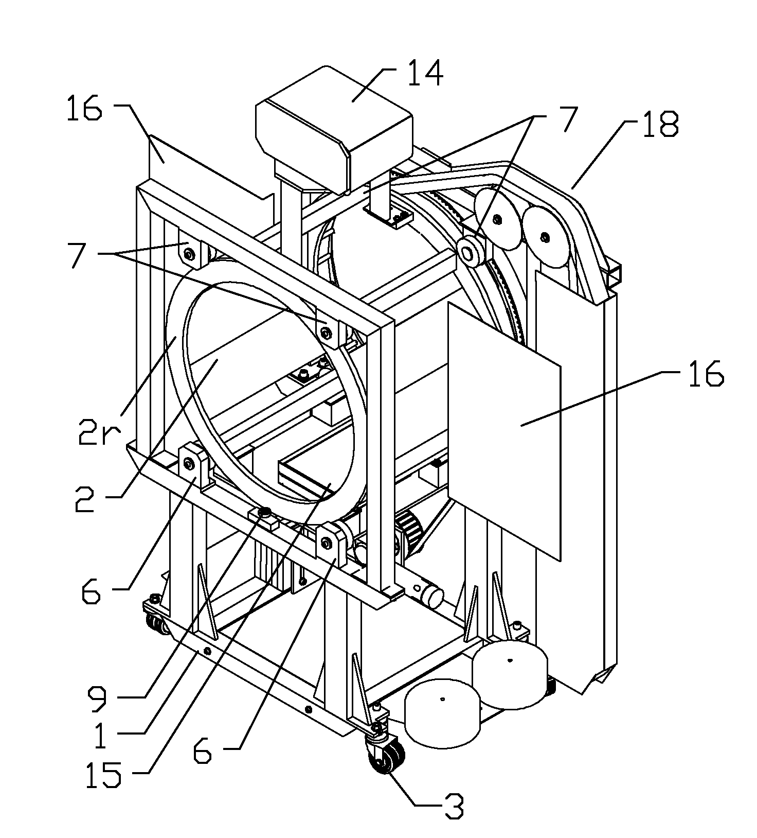
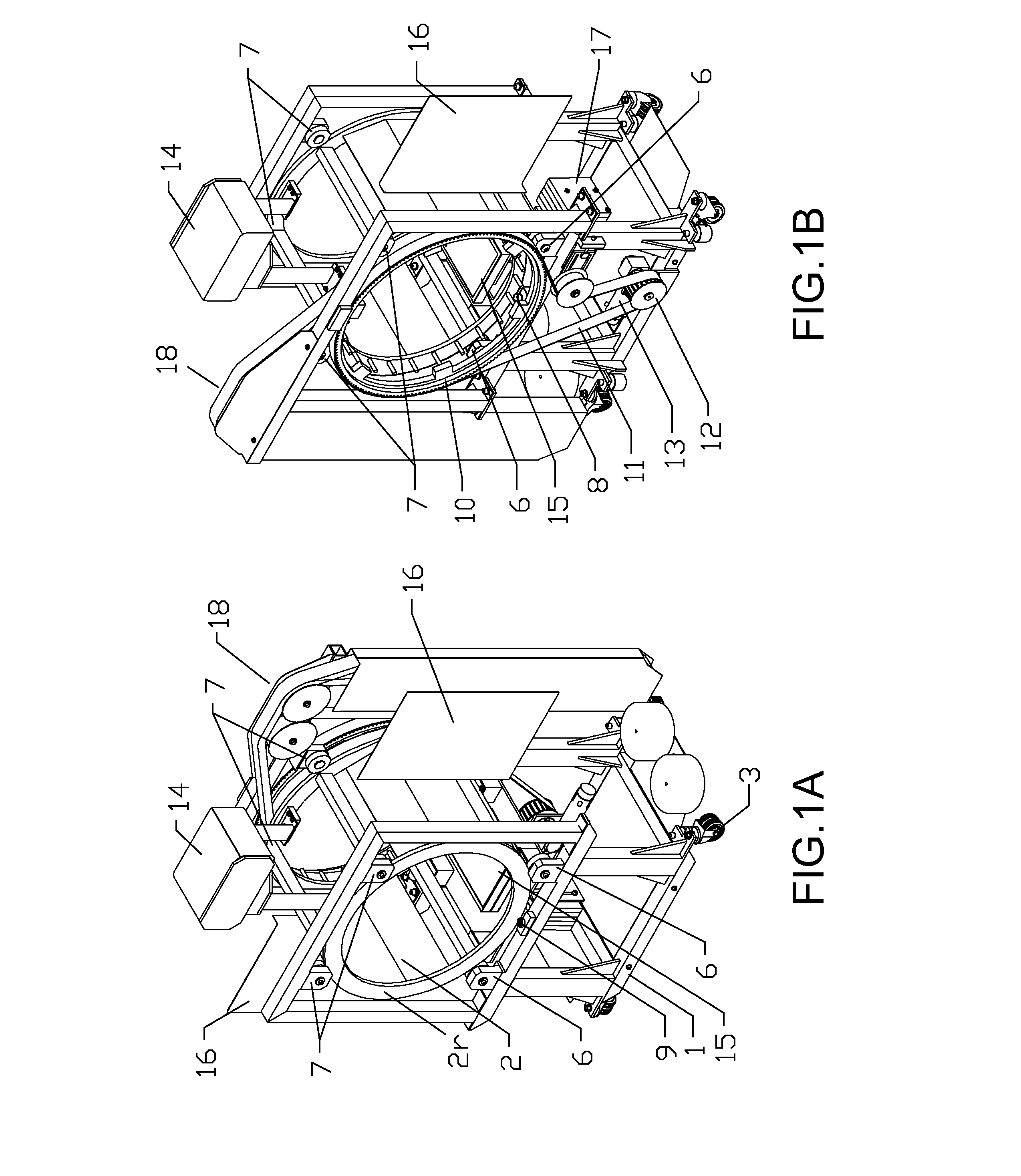
[0013]FIGS. 1A and 1B show a CBCT system comprising a cylindrical gantry. The cylindrical gantry includes a base frame 1 constructed from welded support beams and supporting a rotatable cylindrical frame 2. Components of the cylindrical frame may be manufactured using known milling and welding techniques. The base frame 1 may stand on a floor surface, fixed or not, or be mounted on wheels 3 as shown in the figures.

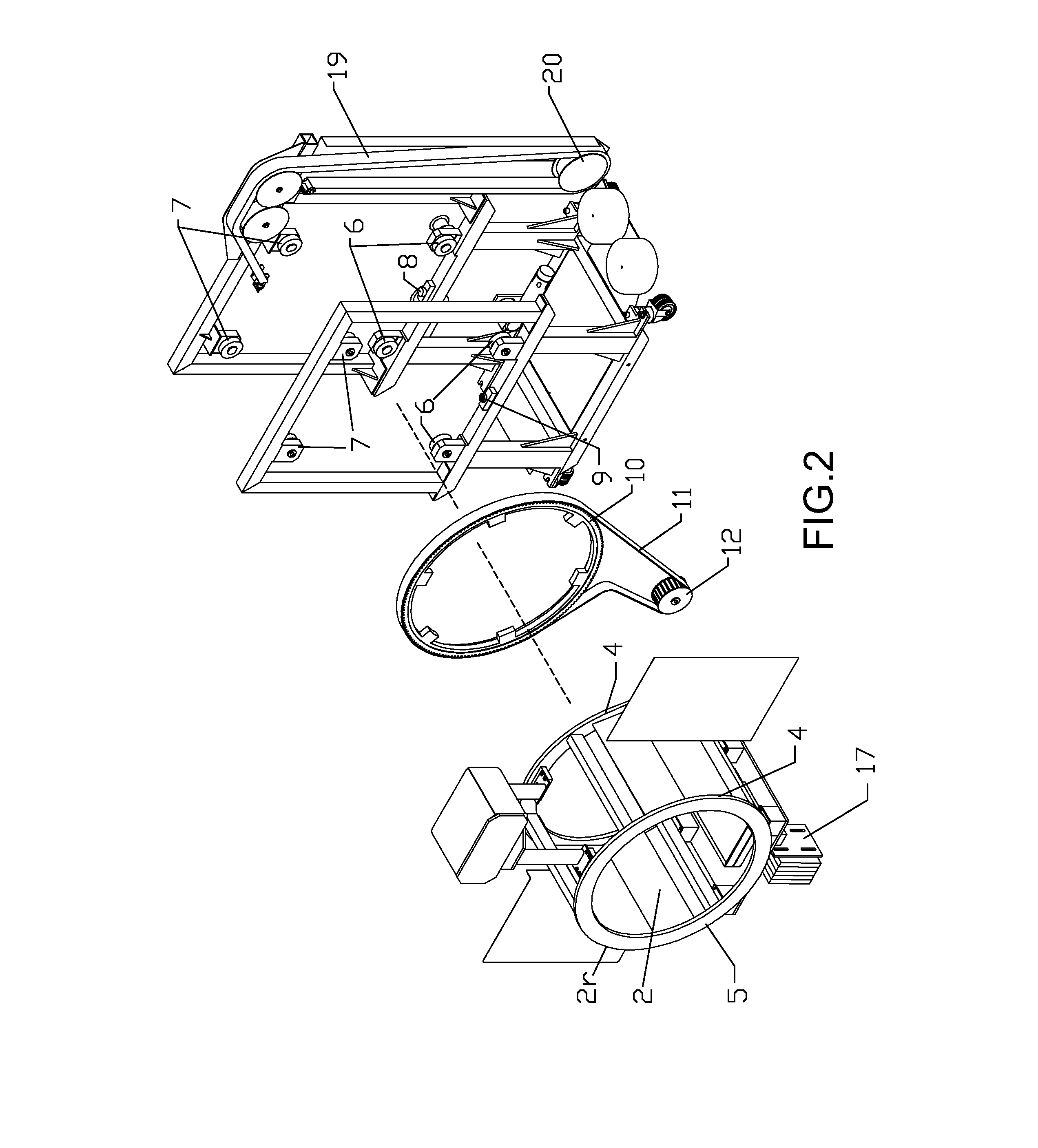
[0014]As shown in FIG. 2 the cylindrical frame 2 has a horizontal axis of rotation. It includes two rotary circular rails 2r, each having a radial surface-guide 4, and an orthogonal rim surface 5, as axial guide. The axial guides 5 are positioned such that their circular cross-sections are orthogonal to the axis of rotation, and they are parallel to each other. Each rotary circular rail 2r is supported by at least two inferior radial rotary bearings 6 from below, and at least two superior radial rotary bearings 7 from above. The rotary bearings 6 are mounted to the base fr...


PUM

PropertyMeasurementUnit
cone beam computed tomographyaaaaaaaaaa
structuresaaaaaaaaaa
computed tomographyaaaaaaaaaa

Abstract

A cone beam computed tomography system with a horizontally disposed, cylindrical gantry and a method for its use are provided. The cylindrical gantry includes a rotatable cylindrical frame fixed to a support frame. A cone beam X-ray source and X-ray detector are mounted to the circumference of the cylindrical frame at diametrically opposed positions. The cylindrical frame is actuated to revolve the X-ray source-detector arrangement around a horizontal axis, thereby scanning a recumbent subject positioned in the aperture of the cylindrical frame.

Description

FIELD OF THE INVENTION[0001]The present invention relates generally to cone beam computed tomography (CBCT), and more particularly, to a method and system whereby a cone beam X-ray source and X-ray detectors are arranged for scanning recumbent subjects in a pass-through gantry.BACKGROUND OF INVENTION[0002]It is known to provide computed tomography (CT) scanning systems with a gantry formed as a centrally apertured disk or drum rotatable within a frame. However, these CT scanners use a two-dimensional fan beam tomography, which is a precursor of three-dimensional CBCT. Fan beam CT scanners are equipped with an array of multiple one-dimensional detector elements that detect a fan-shaped beam of X-rays from a gated radiation source. Three-dimensional image information is acquired by rotating the multi-detector array and X-ray source in a spiral or helical fashion to achieve lateral displacement of the subject and detector array. The need for helical displacement makes gantries for conv...

Claims


Application Information

Patent Timeline
28 Mar 2013
Publication
US20130077737A1
IPC
A61B6/03; G01N23/04
CPC
G01N23/04; A61B6/508; A61B6/4085; A61B6/035
Inventors
FASOLI, MARTINO