Electrical machine having a fan wheel

Active Publication Date: 2013-03-28
SEG AUTOMOTIVE GERMANY GMBH
View PDF3 Cites 1 Cited by
  • Summary
  • Abstract
  • Description
  • Claims
  • Application Information

AI Technical Summary

Benefits of technology

The patent is about a fan impeller used in an electrical machine, specifically in a motor vehicle. The fan impeller is made by inserting a metal or sheet metal part into a mold or die and then injecting plastic onto that part to form the fan blades. This process ensures that the plastic flows through the metal part without being negatively affected by any burrs or recesses. The use of a stamped part as the insert part increases the stability of the fan impeller and makes it suitable for use in high-performance electric machines.

Problems solved by technology

The annular insert part is virtually completely surrounded by the plastic of the blade support ring, this having the disadvantage that, on account of the insulating properties, heat cannot be effectively dissipated, this heat spreading from the shaft on which the fan ring is seated.

Method used


Image

  • Electrical machine having a fan wheel
  • Electrical machine having a fan wheel
  • Electrical machine having a fan wheel

Examples


Embodiment Construction

[0030]In the figures, identical components are provided with the same reference signs.

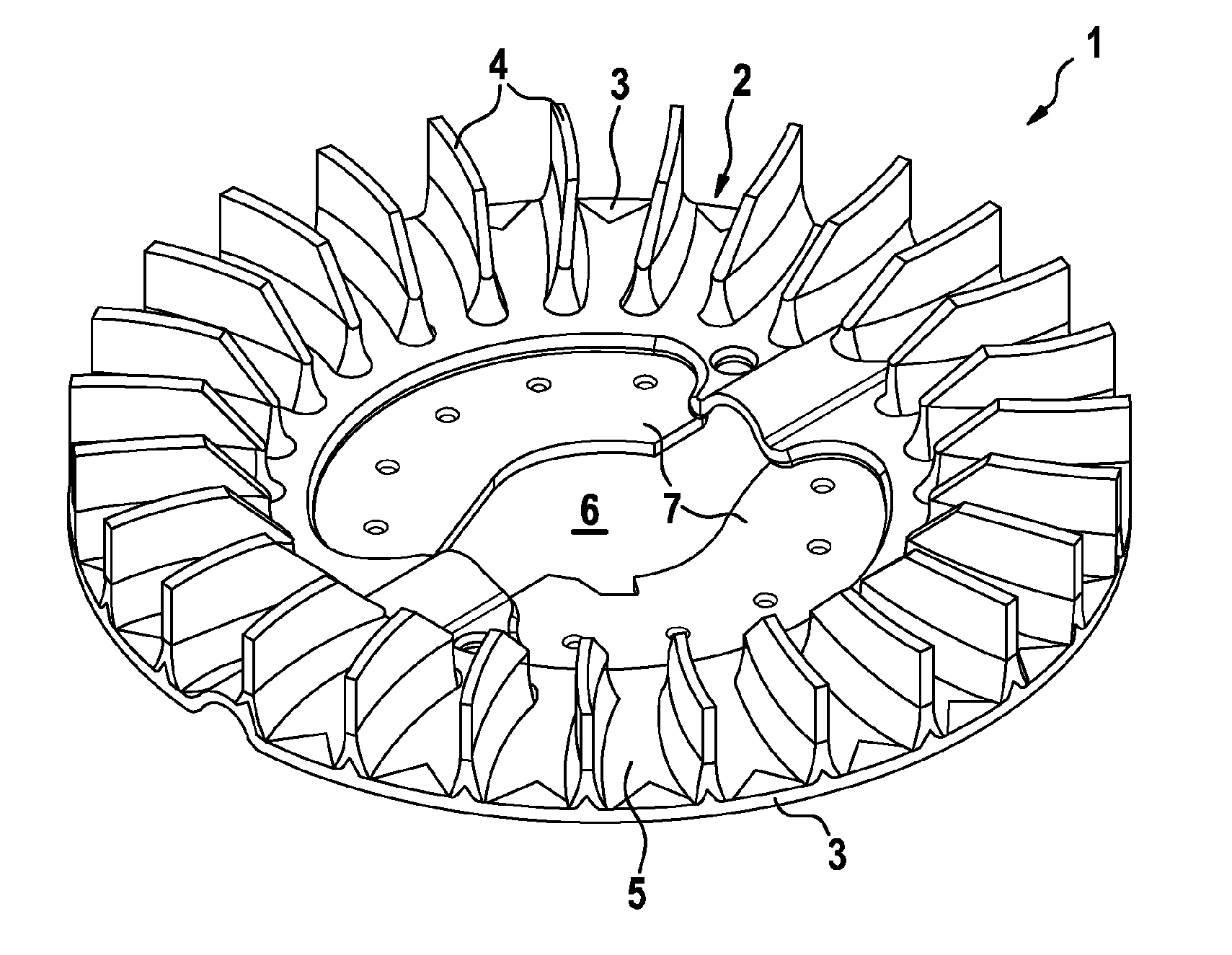
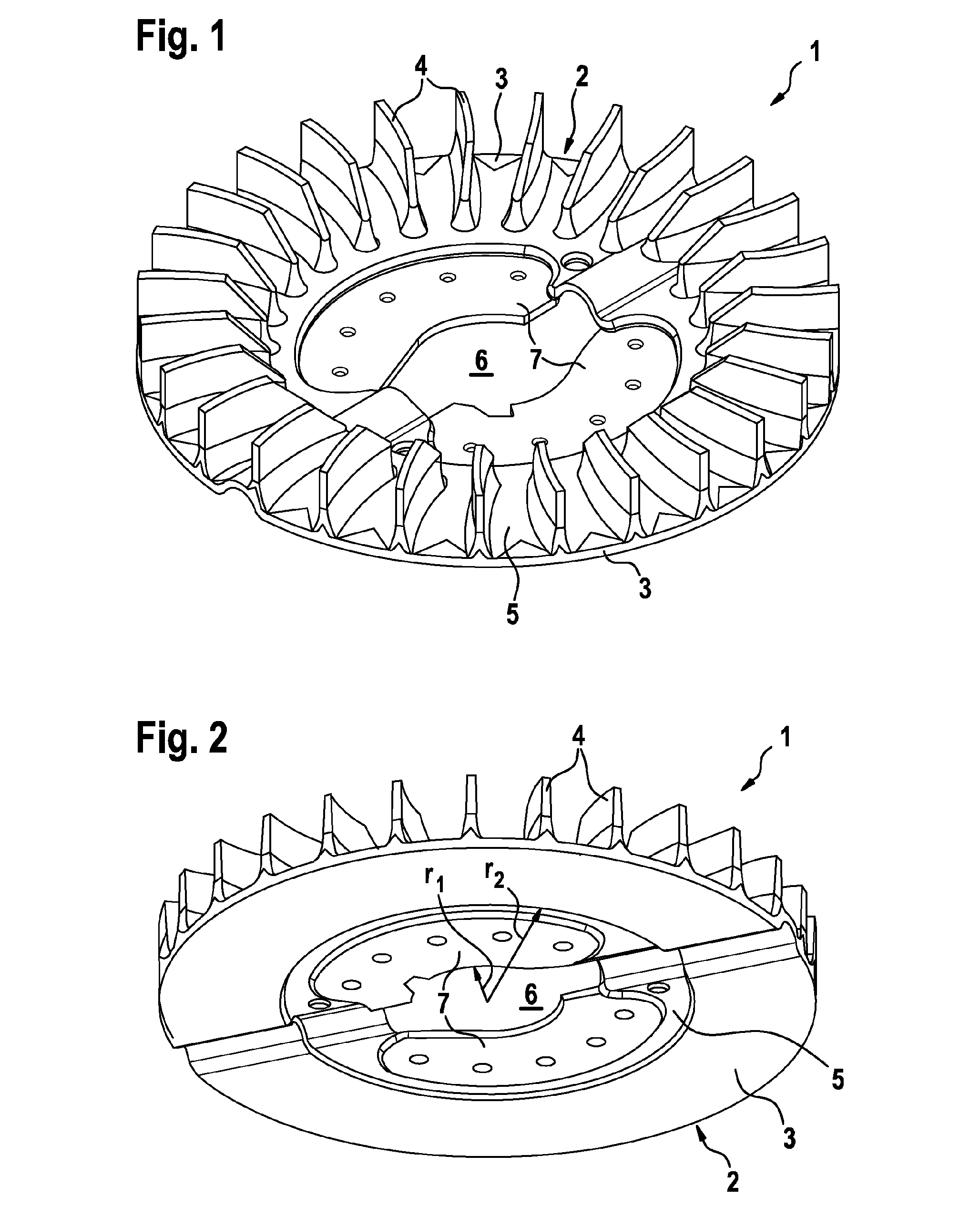
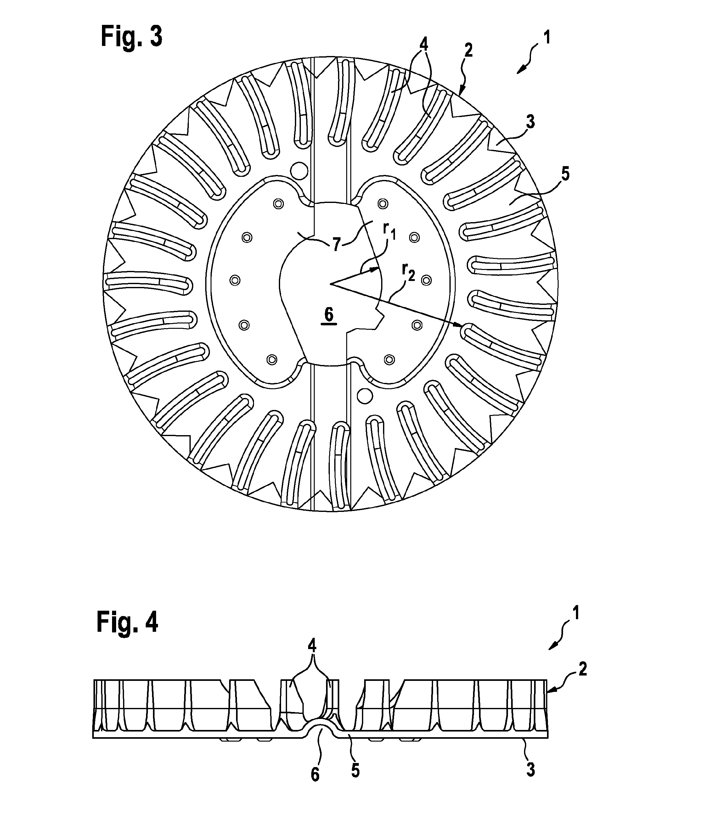
[0031]FIGS. 1 to 6 show a fan impeller 1 for an electrical machine, having a plastic blade support ring 2 having a main body 3 and fan blades 4 and an insert part 5. The blade support ring 2 is mounted on the insert part 5 using an injection-molding process, said insert part being designed as a stamped part and being produced, in particular, for sheet metal or metal. Both the main body 3 of the blade support ring 2 and the insert part 5 are annular and are oriented coaxially to one another and surround a central recess 6 by means of which the fan impeller 1 is mounted on a supporting shaft. The central recess 6 is bounded directly by boundary sections 7 which are integrally formed with the insert part 5.

[0032]The main body 3 of the plastic blade support ring 2 is annular and covers the lower face of the insert part 5 which is situated opposite the blade side, in an annular strip. In addition, the m...


PUM

PropertyMeasurementUnit
Diameteraaaaaaaaaa
Radiusaaaaaaaaaa

Abstract

The invention relates to an electrical machine having a fan wheel which comprises an injection-moulded blade carrier ring with fan blades as well as an annular insertion part which is integrated into the blade carrier ring and which comprises passage openings via which the blade carrier ring is connected to the fan blades.

Description

BACKGROUND OF THE INVENTION[0001]The invention relates to an electrical machine having a fan impeller.[0002]AC generators for motor vehicles which are cooled with the aid of a fan impeller during operation in order to be able to maintain a temperature at which optimum power is ensured are known. A generator of this kind which is provided with a fan impeller is described, for example, in DE 692 01 498 T2. The fan impeller which is known from said document comprises an annular metal insert part and a blade support ring which is in the form of a molded plastic part and has fan blades. The blade support ring is formed on the metal insert part which has a central recess in order to be mounted on a shaft. The annular insert part is virtually completely surrounded by the plastic of the blade support ring, this having the disadvantage that, on account of the insulating properties, heat cannot be effectively dissipated, this heat spreading from the shaft on which the fan ring is seated.[0003...

Claims


Application Information

Patent Timeline
IPC IPC(8): F04D29/28
CPCB29C45/14311B29C2045/14327B29L2031/08Y10T29/49336F04D29/281H02K9/06F04D29/263
Inventor DIKMENLI, ERDOGAN
Owner SEG AUTOMOTIVE GERMANY GMBH
Why Eureka
Try Eureka