Supercharge Your Innovation With Domain-Expert AI Agents!

Valve Frame

a technology for supporting frames and prosthetics, applied in the field of valve frames, can solve the problems of inability to treat the underlying disease, affecting the ability of individuals to perform in the workplace or maintain, and the valve can become incompetent, so as to improve the symmetrical distribution of stress-strain forces and improve contact.

Active Publication Date: 2013-03-28
COOK MEDICAL TECH LLC
View PDF27 Cites 66 Cited by
  • Summary
  • Abstract
  • Description
  • Claims
  • Application Information

AI Technical Summary

Benefits of technology

The support frame effectively maintains vein patency, reduces irritation, and ensures durable valve function by distributing stress and strain forces, preventing migration and wear on the valve leaflets, thus addressing the dynamic challenges of venous flow.

Problems solved by technology

The failure of native valves to properly close can worsen, leading to significant leakage of retrograde flow such that the valve can become incompetent.
Elevation of the feet and compression stocking can relieve symptoms, but do not treat the underlying disease.
Untreated, the disease can impact the ability of individuals to perform in the workplace or maintain their normal lifestyle.
However, dynamic fluctuations in the shape of the vein pose challenges to the design of implantable devices that conform to the interior shape of the vein.
These conditions may present challenges to designing an implantable frame suitable for placement inside the vein.
An implantable frame lacking sufficient radial strength may collapse and / or fracture under the repeated fluctuations of vein diameter, while an implantable frame with undesirably high levels of radial strength may lack flexibility and may damage the vein by failing to compress in response to normal fluctuations in the vein diameter.
Likewise, an implantable frame with a high surface area contacting the interior wall of a vein may induce inflammation or trauma in the vein wall, while an implantable frame with an insufficient surface area may lack sufficient durability.

Method used


Image

  • Valve Frame
  • Valve Frame
  • Valve Frame

Examples


Embodiment Construction

[0025]Unless otherwise defined, all technical and scientific terms used herein have the same meaning as commonly understood by one of ordinary skill in the art to which this disclosure pertains. In case of conflict, the present document, including definitions, will control. Preferred methods and materials are described below, although methods and materials similar or equivalent to those described herein can be used in the practice or testing of the present disclosure. All publications, patent applications, patents and other references mentioned herein are incorporated by reference in their entirety. The materials, methods, and examples disclosed herein are illustrative only and not intended to be limiting.

DEFINITIONS

[0026]The terms “proximal” and “distal” will be used to describe the opposing axial ends of the medical device, as well as the axial ends of various component features. The term “proximal” is used in its conventional sense to refer to the end of the device (or component ...


PUM


Abstract

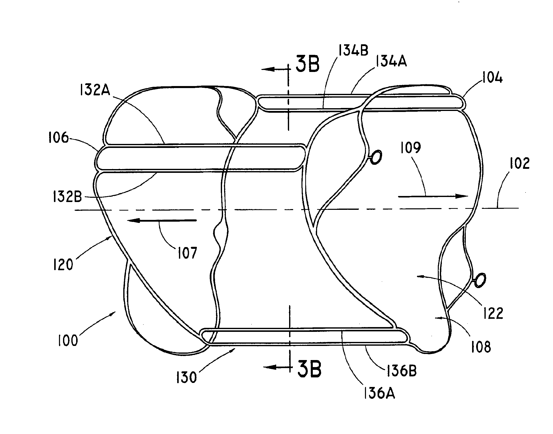
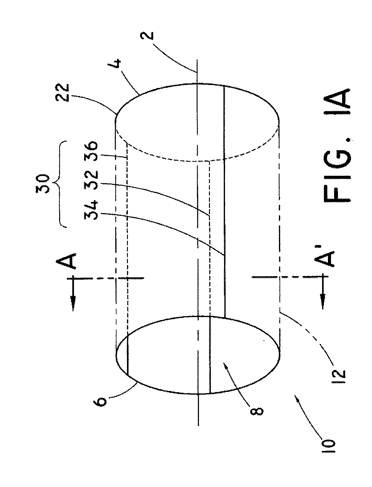
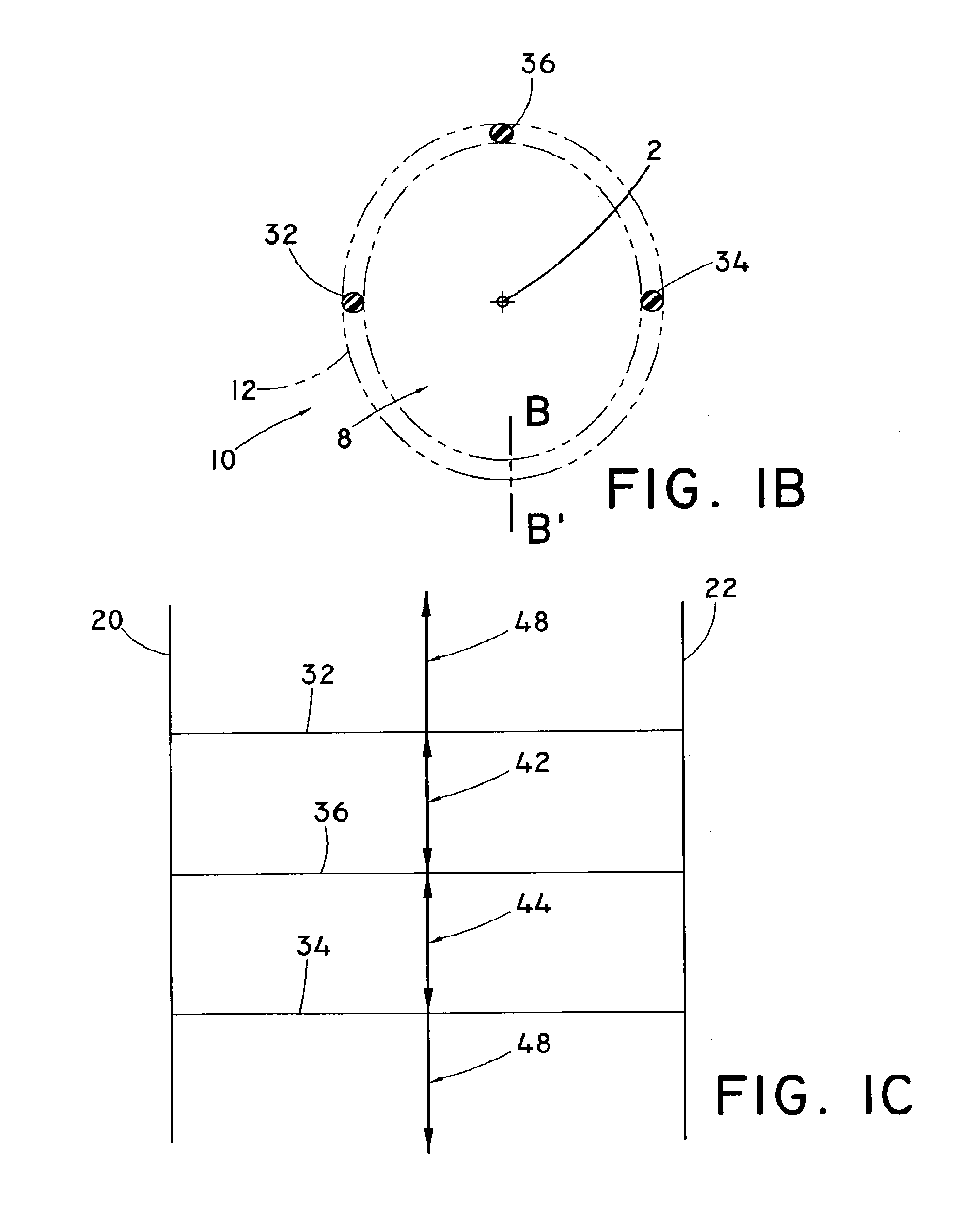
The disclosure relates to support frames for prosthetic implantable valves. The support frames may include a plurality of symmetrically arrayed interconnected U-shaped member structures. Preferred support frames are tubular structures enclosing a longitudinal axis and including a plurality of U-shaped member structures facing a distal or a proximal end of the support frame. Each U-shaped member structure may be connected to a single longitudinally adjacent U-shaped member facing in an opposite longitudinal direction, as well as two laterally adjacent U-shaped members.

Description

PRIORITY CLAIM[0001]This application is a continuation of U.S. patent application Ser. No. 12 / 273,168, which was filed on Nov. 18, 2008 and claims the benefit of U.S. Provisional Patent Application No. 60 / 988,987, filed Nov. 19, 2007. The entire contents of each of these related applications are hereby incorporated by reference into this disclosure.TECHNICAL FIELD[0002]The present disclosure relates to support frames for prosthetic implantable valves adapted for percutaneous implantation within a body vessel, as well as methods of treatment pertaining to the implantation of the prosthetic valves and methods of manufacturing prosthetic valvesBACKGROUND OF THE DISCLOSURE[0003]Intraluminally implantable frames may be implanted to treat a variety of conditions in a variety of fields. Frames implanted in vessels, ducts or channels of the human body can form part of a valve to regulate fluid flow within a body lumen or as scaffolding to maintain the patency of the vessel, duct or channel ...

Claims


Application Information

Patent Timeline
Patent Type & Authority Applications(United States)
IPC IPC(8): A61F2/24
CPCA61F2/2418A61F2/2475A61F2220/0058A61F2220/0016A61F2220/005A61F2220/0008A61F2/24A61F2/2476
Inventor HOFFMAN, GRANT T.CHAMBERS, SEAN D.PAUL, RAM H.
Owner COOK MEDICAL TECH LLC
Features
  • R&D
  • Intellectual Property
  • Life Sciences
  • Materials
  • Tech Scout
  • Unparalleled Data Quality
  • Higher Quality Content
  • 60% Fewer Hallucinations
Learn More