Error cause detection or narrowing down of errors with the aid of error patterns in the air system

Inactive Publication Date: 2013-03-28
ROBERT BOSCH GMBH
View PDF14 Cites 2 Cited by
  • Summary
  • Abstract
  • Description
  • Claims
  • Application Information

AI Technical Summary

Benefits of technology

[0024]By calculating the variable from model variables and measured variables, it is possible to select, for the characteristic to be monitored, an easily understandable and comprehensible variable whose values are easily interpretable and understandable to a technician during the repair of the internal combustion engine so that these values may provide other important information regarding a quick narrowing down of the error cause.
[0025]In one refinement of the exemplary embodiments and/or exemplary methods of the present invention, the observation device for assigning the actual values to the corresponding operating states in the actual pattern and the evaluation device for comparing the actual pattern to the reference pattern may be provided in the method according to the present invention or i

Problems solved by technology

As soon as the air system is transferred into this established operating range, the characteristic is compared to the boundaries and an error is detected in the case of (permanent) exceedance of the boundaries.
Such common monitoring functions, however, monitor the air system only for their correct function and detect a malfunction per se.
If a malfunction of the air system is determined, such common monitoring functions are presently not capable of qualifying this error.
This makes the error diagnosis and the error cause investigation more diffi

Method used


Image

  • Error cause detection or narrowing down of errors with the aid of error patterns in the air system
  • Error cause detection or narrowing down of errors with the aid of error patterns in the air system
  • Error cause detection or narrowing down of errors with the aid of error patterns in the air system

Examples


Embodiment Construction

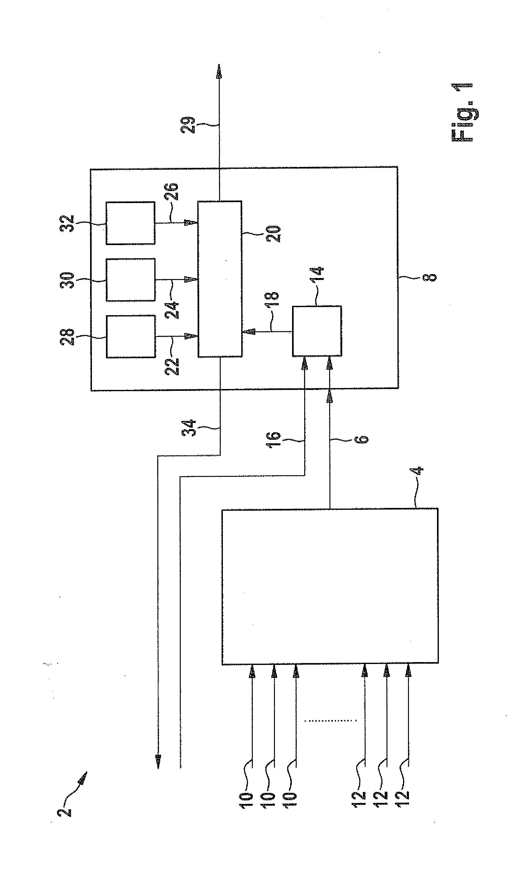
[0038]FIG. 1 shows the block diagram of a monitoring function 2 of a device according to the present invention. Monitoring function 2 is implementable in an arithmetic unit (not shown). In a vehicle, such an arithmetic unit is provided by the engine control unit, for example, which may thus also execute monitoring function 2.

[0039]Monitoring function 2 includes a model 4 and an evaluation device 8. Based on the values of different measured variables 10 and model variables 12, model 4 calculates a monitoring variable 6 which is made available to the comparison section. The values of measured variables 10 are delivered by sensors (not shown) in an internal combustion engine (not shown). Model variables 12 describe boundary conditions using which the at least one part of the internal combustion engine, such as air system 46 of the internal combustion engine which is explained later with reference to FIG. 4, may be simulated.

[0040]The exemplary embodiments and / or exemplary methods of th...


PUM


Abstract

A method for monitoring at least one part of an internal combustion engine based on a variable whose values characterize the operation of the part of the internal combustion engine during different states of the internal combustion engine, including: determining an actual pattern with the actual values of the variable during different states of the internal combustion engine which describe the actual operation of the internal combustion engine; providing a reference pattern for a known operation of the internal combustion engine, the reference pattern including reference values of the variable for different states of the internal combustion engine; and comparing the actual pattern to the reference pattern to determine a similarity between the actual operation and the known operation.

Description

RELATED APPLICATION INFORMATION[0001]The present application claims priority to and the benefit of German patent application no. 10 2011 083 587.3, which was filed in Germany on Sep. 28, 2011, the disclosure of which is incorporated herein by reference.FIELD OF THE INVENTION[0002]The present invention relates to error detection in internal combustion engines.BACKGROUND INFORMATION[0003]On board diagnostic systems are known from the automotive technology. These systems are vehicle diagnostic systems which monitor all emission-influencing systems during the operation and store possibly arising errors in a memory so that they may be queried and, if necessary, eliminated.[0004]Common monitoring functions in the air system for internal combustion engines are in most cases configured in such a way that a characteristic (for example, system deviation) is determined from inputs (sensors, model values, . . . ) under certain release conditions used to establish an operating range. For this pu...

Claims


Application Information

Patent Timeline
IPC IPC(8): G06F19/00F02D28/00G16Z99/00
CPCG06F19/00F02D28/00G01M15/042F02D41/0072G06F19/328F02D41/26F02D2200/0402F02D2200/0406F02D2200/0411F02D41/22G16Z99/00
Inventor BLEILE, THOMASMICHAEL, STEFANMONTVAY, ANDRASHOEPFNER, CHRISTINARINGEISEN, MARC
Owner ROBERT BOSCH GMBH
Why Eureka
Try Eureka