

Circuits, devices, methods and systems to secure power-up for battery operating devices even with low current chargers and to execute other performances
a technology of integrated circuits and operating devices, applied in electric power, electric vehicles, transportation and packaging, etc., can solve the problems of marginal or low-cost charger adapters not meeting any particular standards, insufficient power for some devices or in some scenarios, and host being prevented from charging
- Summary
- Abstract
- Description
- Claims
- Application Information
AI Technical Summary
Benefits of technology
Problems solved by technology
Method used
Image

Examples
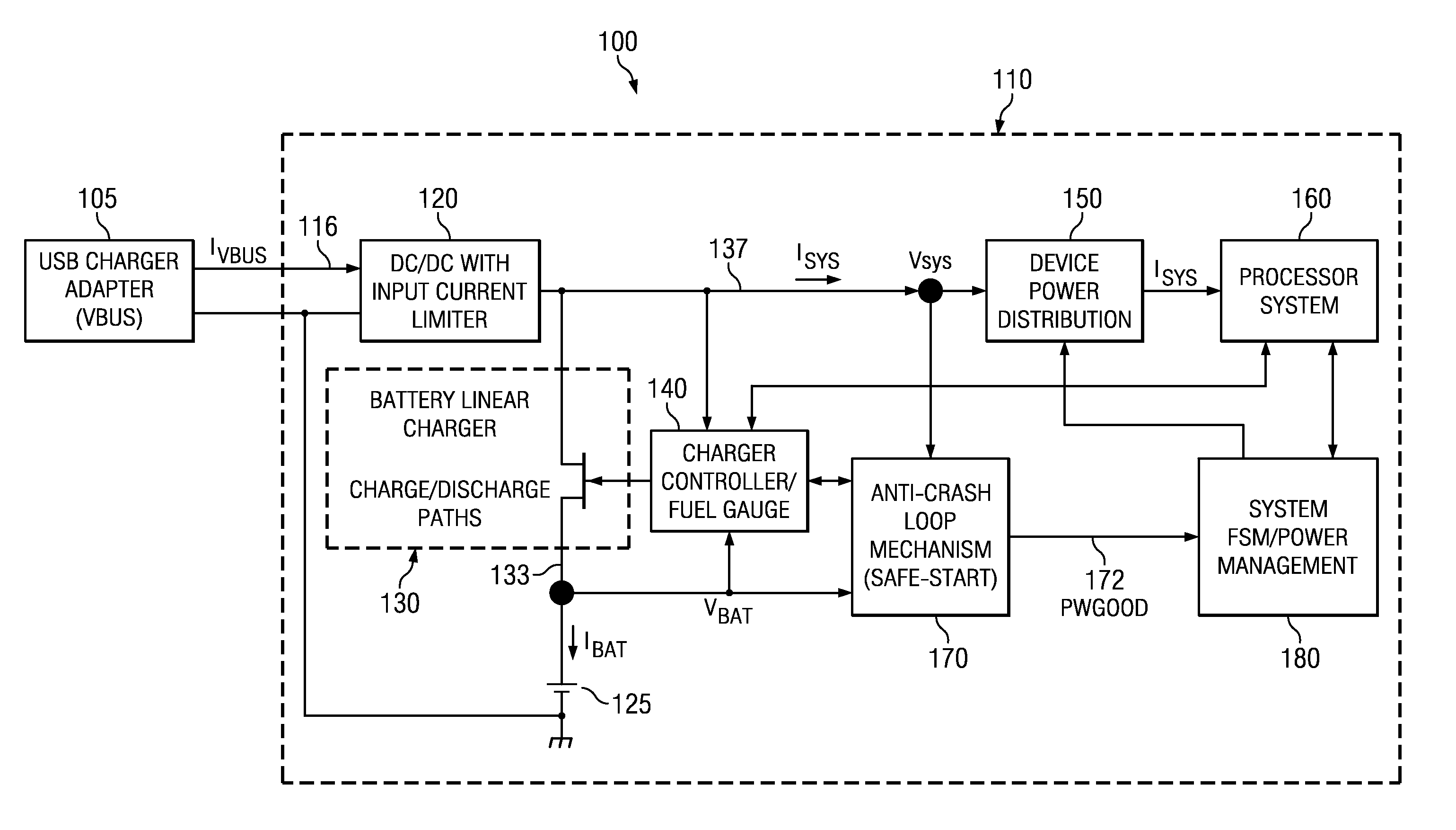
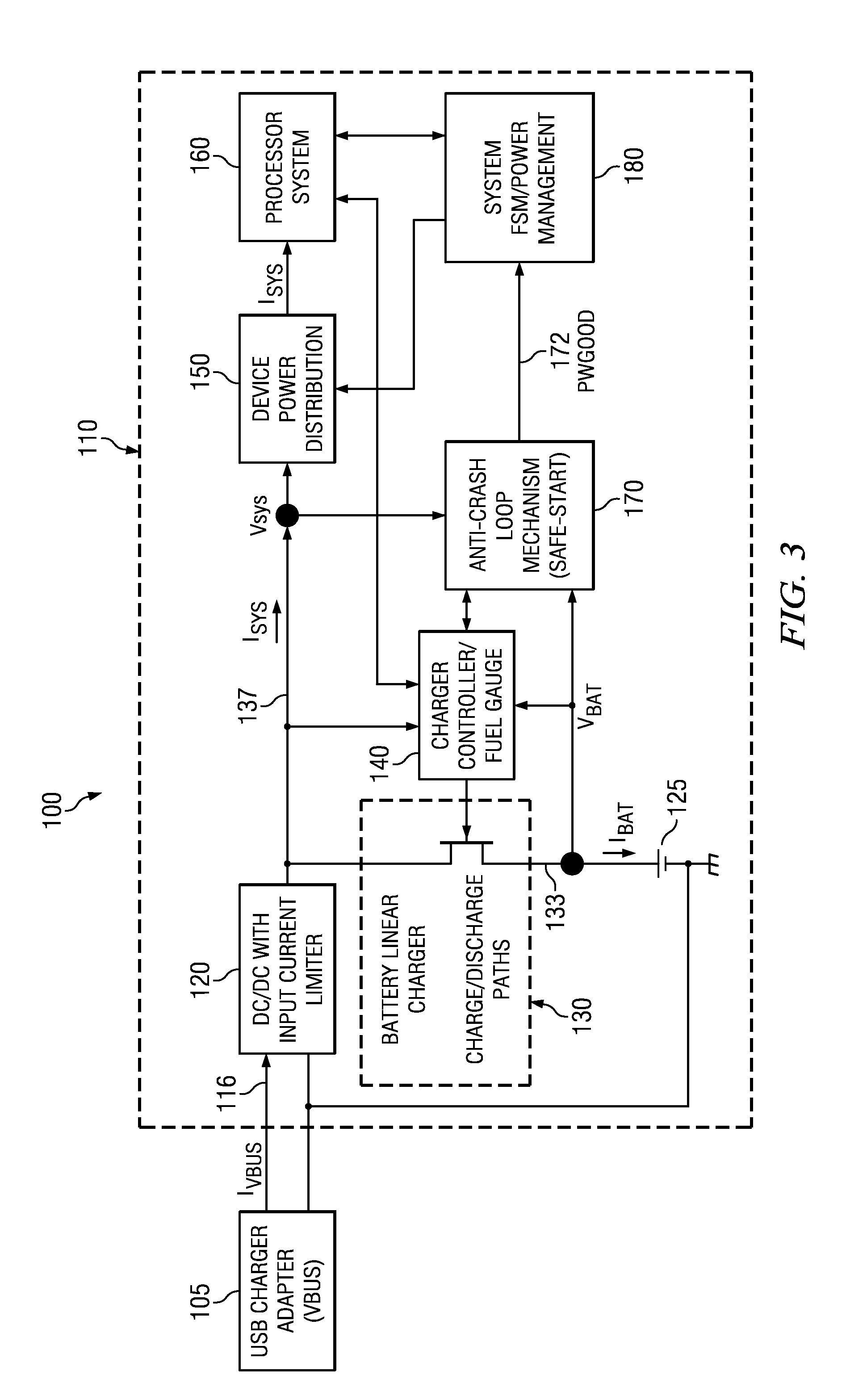
embodiment 110
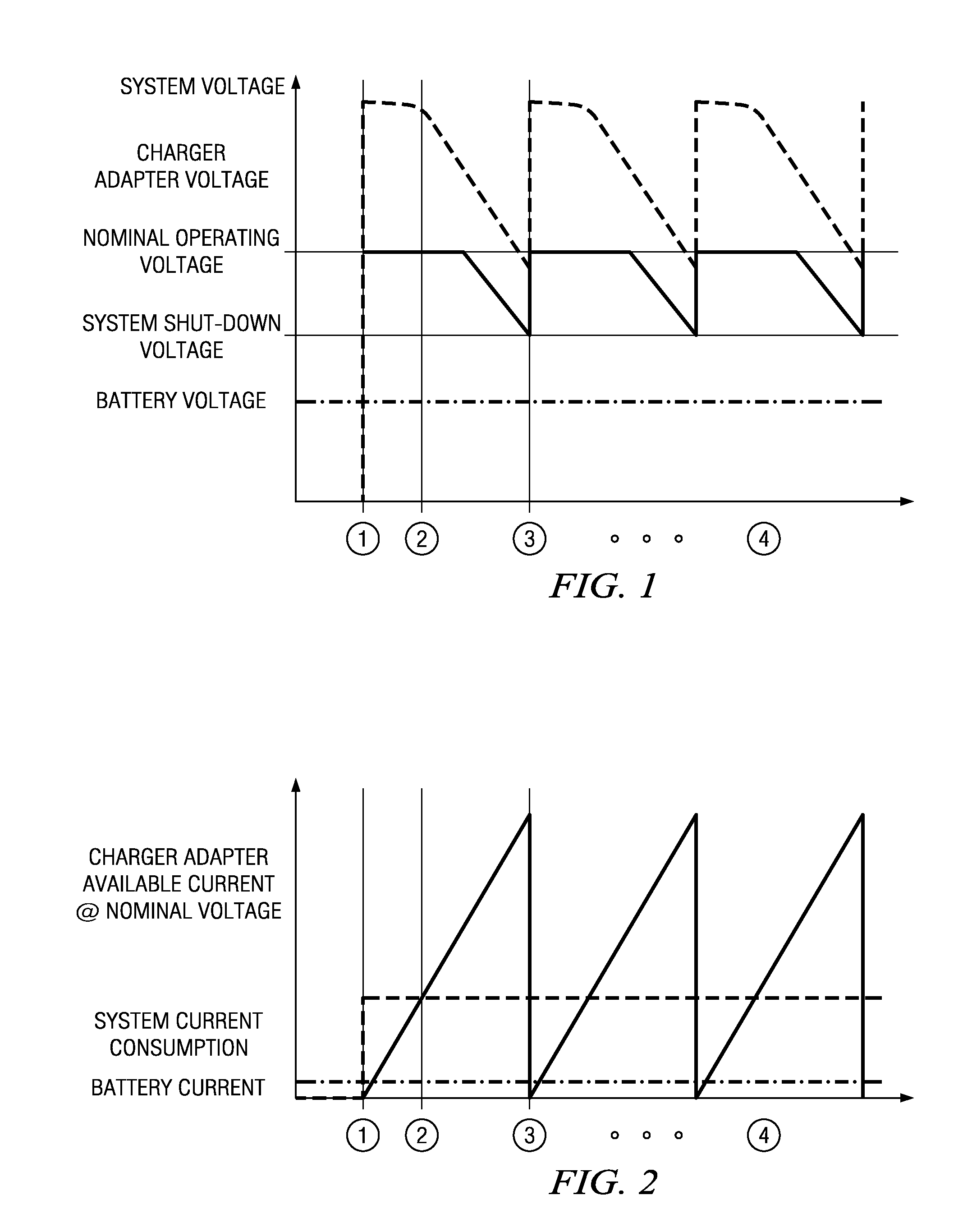
[0064]In FIGS. 3-8, a device embodiment 110 with an anti-crash-loop mechanism 170 in combination as shown prevents overall system instability in problematic conditions that could otherwise occur as discussed for FIGS. 1-2. The anti-crash-loop mechanism 170 has a state machine 178 or 278 or other such control circuitry, that constantly monitors system voltage VSYS when VBAT is below Vbatminhi even when a charger 105 is connected. In such case a power-good control line 172 supplies a PWGOOD signal output or indicator active (e.g., low) to at least briefly attempt to operate the system. If VSYS comes to drop below Vsysminlo and external charger 105 voltage is collapsing, this is a crash condition and PWGOOD output goes high impedance (inactive, decoupling the system from most or all power) and this makes or lets the system voltage VSYS rise in magnitude. Then PWGOOD stays inactive high (=1) and battery charging current IBAT is thereby maximized and continued until battery voltage VBAT ...
embodiment 170
[0071]Turning to FIG. 4, an anti-crash-loop mechanism embodiment 170 implements, for example, three (3) voltage comparators 171, 172, 173, a time-out timer 176 and Safe-Start Finite State Machine 178 of FIG. 5. Comparators 171, 172, 173 are coupled at respective outputs to inputs to the Safe-Start Finite State Machine 178. Comparator reference Ref thresholds for FIG. 4 comparators 171, 172, 173 are defined for example as follows. Different definitions can be used in some other embodiments and types of performances.
[0072]Vsysminhi reference for comparator 171 is set to a high enough value of system supply voltage to be useful for possible turn-on purposes and below which the system is able to operate at least for a while successfully as system voltage declines after turn-on. Comparator 171 has its other input fed with the actual voltage VSYS itself. System 110 is authorized to power-up (so that PWGOOD goes active e.g., low) when VSYS goes above this threshold when running from input ...
embodiment 300
[0132]In FIG. 9, another protective safe-start system embodiment 300 has a safe-starting anti-crash-loop mechanism 370 (170) integrated into a Fuel Gauge controller 340, and in combination they together continuously monitor Battery voltage VBAT and System Supply voltage VSYS and fuel-gauge level X % ChargeLevel for controlling power management state machine 380. Interaction or coupling with processor system 360 provides the PWGOOD signal from a safe-start state machine (e.g. 178, 278, or otherwise) in anti-crash-loop mechanism 370 to a processor system power management state machine 380 as an important one of the power-on / power-off conditions. The PWGOOD signal is used to allow the system 360 to power-up or to force power management state machine 380 to an Off state or other appropriate state instead. Safe-starting anti-crash-loop mechanism 370 in some embodiments is thus made part of a fuel-gauge controller 340 to economically benefit by resource-sharing of voltage measurement func...
PUM
 Abstract
Description
Claims
Application Information