Oscillation circuit and operating current control method thereof

Active Publication Date: 2013-04-04
MITSUMI ELECTRIC CO LTD
View PDF12 Cites 4 Cited by
  • Summary
  • Abstract
  • Description
  • Claims
  • Application Information

AI Technical Summary

Benefits of technology

[0017]For example, with an embodiment of the pre

Problems solved by technology

Therefore, the oscillation circuit of the relate

Method used


Image

  • Oscillation circuit and operating current control method thereof
  • Oscillation circuit and operating current control method thereof
  • Oscillation circuit and operating current control method thereof

Examples


first embodiment

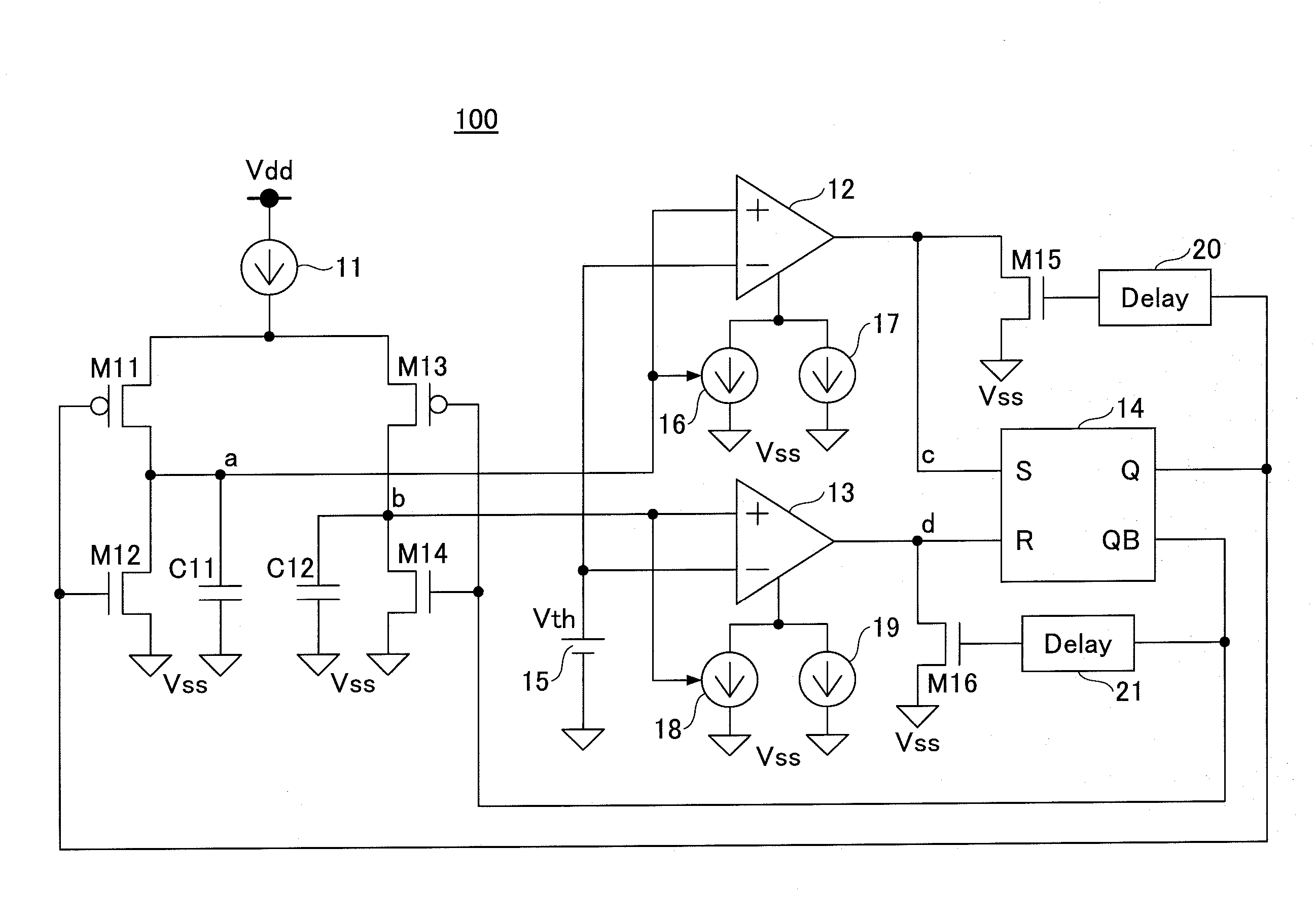
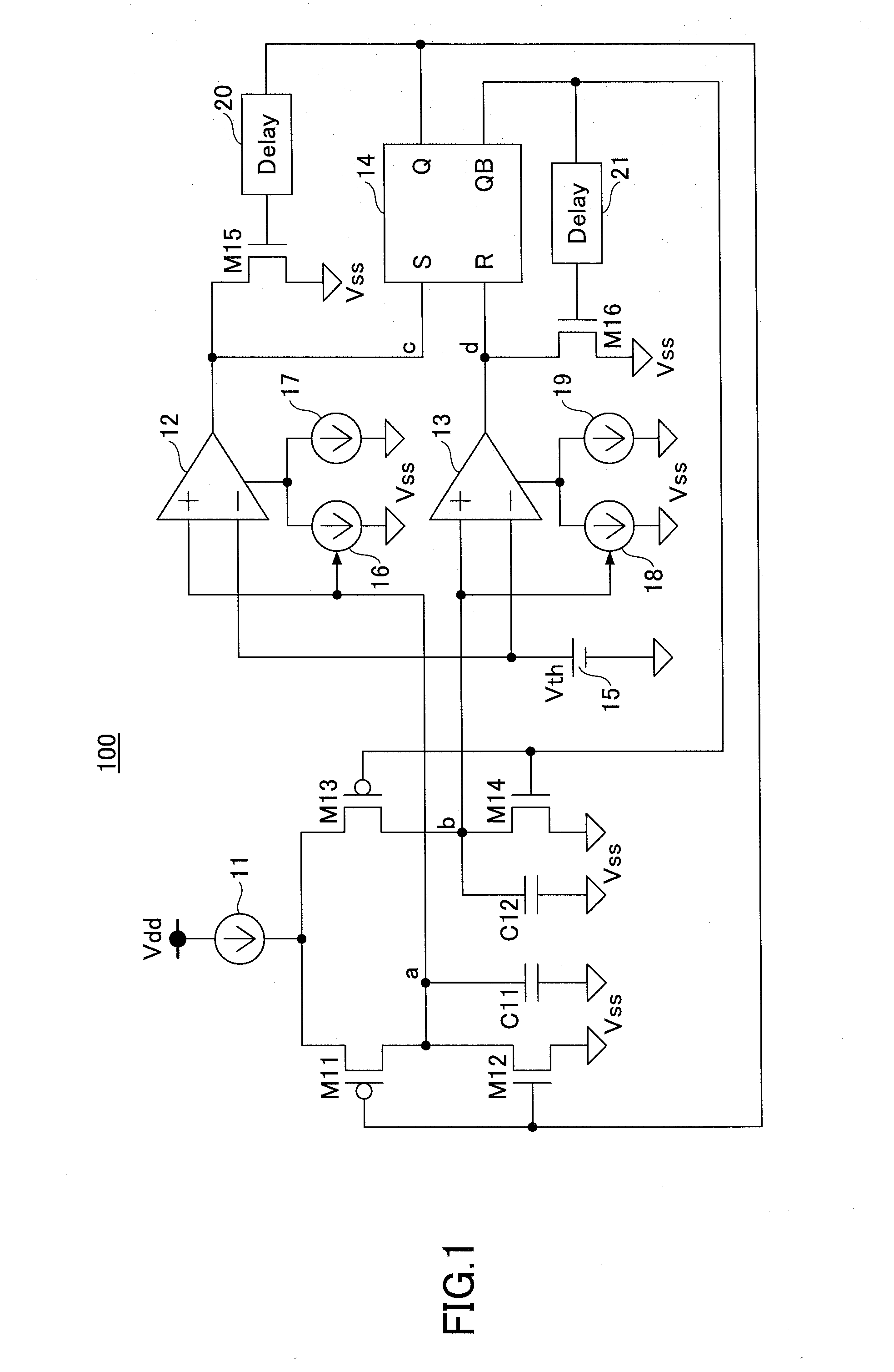
[0037]FIG. 1 is a circuit configuration diagram of an oscillation circuit 100 according to the first embodiment of the present invention. In FIG. 1, a constant current source 11 has one end connected to a power supply Vdd and another end connected to the sources of p-channel MOS transistors M11, M13. A drain of the MOS transistor M11 is connected to a drain of an n-channel MOS transistor. A source of the MOS transistor M12 is connected to a power supply Vss. Further, a drain of the MOS transistor M13 is connected to a drain of an n-channel MOS transistor M14. A source of the MOS transistor M14 is connected to the power supply Vss.

[0038]The drains of the MOS transistors M11, M12 are connected to one end of a condenser C11 and also connected to a non-inverting input terminal of a comparator 12 and a control terminal of a current source 16. The other end of the condenser C11 is connected to the power supply Vss. The gates of the MOS transistors M11, M12 are connected to a Q terminal of...


PUM


Abstract

An oscillation circuit includes a condenser, a charging/discharging part configured to switch between charging and discharging of the condenser according to a control signal, a comparator configured to compare a voltage of the condenser with a reference voltage and output a comparison result signal, a flip-flop configured to be set or reset according to the comparison result signal, supply an output signal as the control signal to the charging/discharging part, and output the output signal as an oscillation signal, and a current control part configured to control an operating current of the comparator in correspondence with the voltage of the condenser.

Description

TECHNICAL FIELD[0001]The present invention relates to an oscillation circuit and an operating current control method thereof.BACKGROUND ART[0002]FIG. 9 is a circuit configuration diagram illustrating an example of an oscillation circuit according to a related art example. In FIG. 9, a constant current source 1 has one end connected to a power supply Vdd and another end connected to the sources of p channel MOS transistors M1, M3. A drain of the MOS transistor M1 is connected to a drain of an n channel MOS transistor M2. A source of the MOS transistor M2 is connected to a power supply Vss. A drain of the MOS transistor M3 is connected to a drain of an n channel MOS transistor M4. A source of the MOS transistor M4 is connected to the power supply Vss.[0003]The drains of the MOS transistors M1, M2 are connected to one end of a condenser C1 and also connected to a non-inverting input terminal of a comparator 2. The other end of the condenser C1 is connected to the power supply Vss. The ...

Claims


Application Information

Patent Timeline
IPC IPC(8): H03K3/36
CPCH03K3/36H03K3/011H03K3/0231
Inventor INOUE, FUMIHIRO
Owner MITSUMI ELECTRIC CO LTD
Why Eureka
Try Eureka