Mutual Inductance Circuits

a technology of inductors and circuits, applied in the field of integrated circuits, can solve the problems of difficult to achieve low-noise, high-q (e.g., q>20) lc oscillator with conventional integrated circuit techniques, and the inductors of the lc oscillator circuits are susceptible to electromagnetic interferen

Active Publication Date: 2013-04-04
SILICON LAB INC
View PDF3 Cites 13 Cited by
  • Summary
  • Abstract
  • Description
  • Claims
  • Application Information

AI Technical Summary

Problems solved by technology

However, in those integrated circuit applications, a low-noise, high-Q (i.e., quality factor) LC oscillator is typically required.
It is difficult to achieve a low-noise, high Q (e.g., Q>20) LC o

Method used


Image

  • Mutual Inductance Circuits
  • Mutual Inductance Circuits
  • Mutual Inductance Circuits

Examples


Embodiment Construction

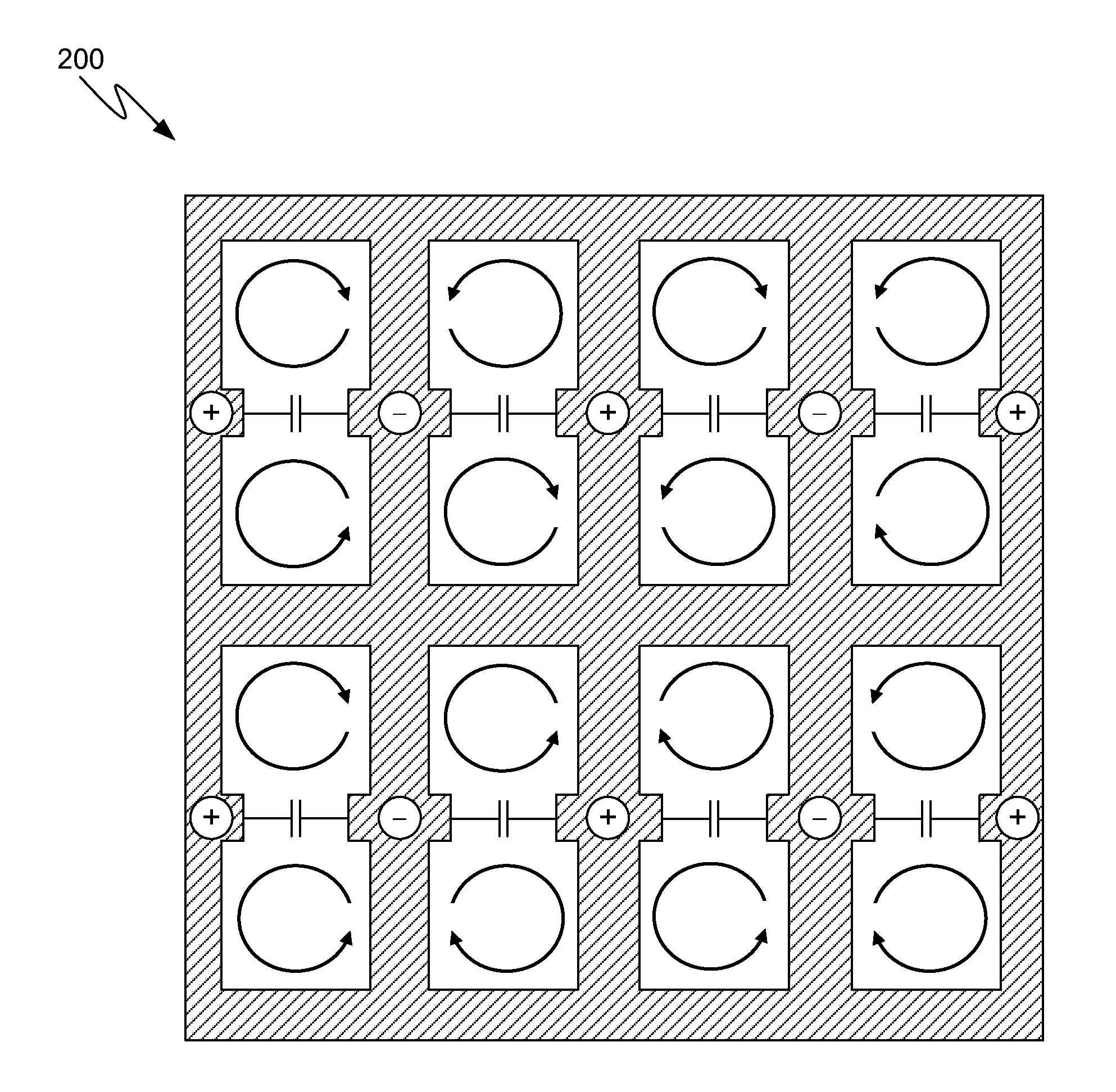
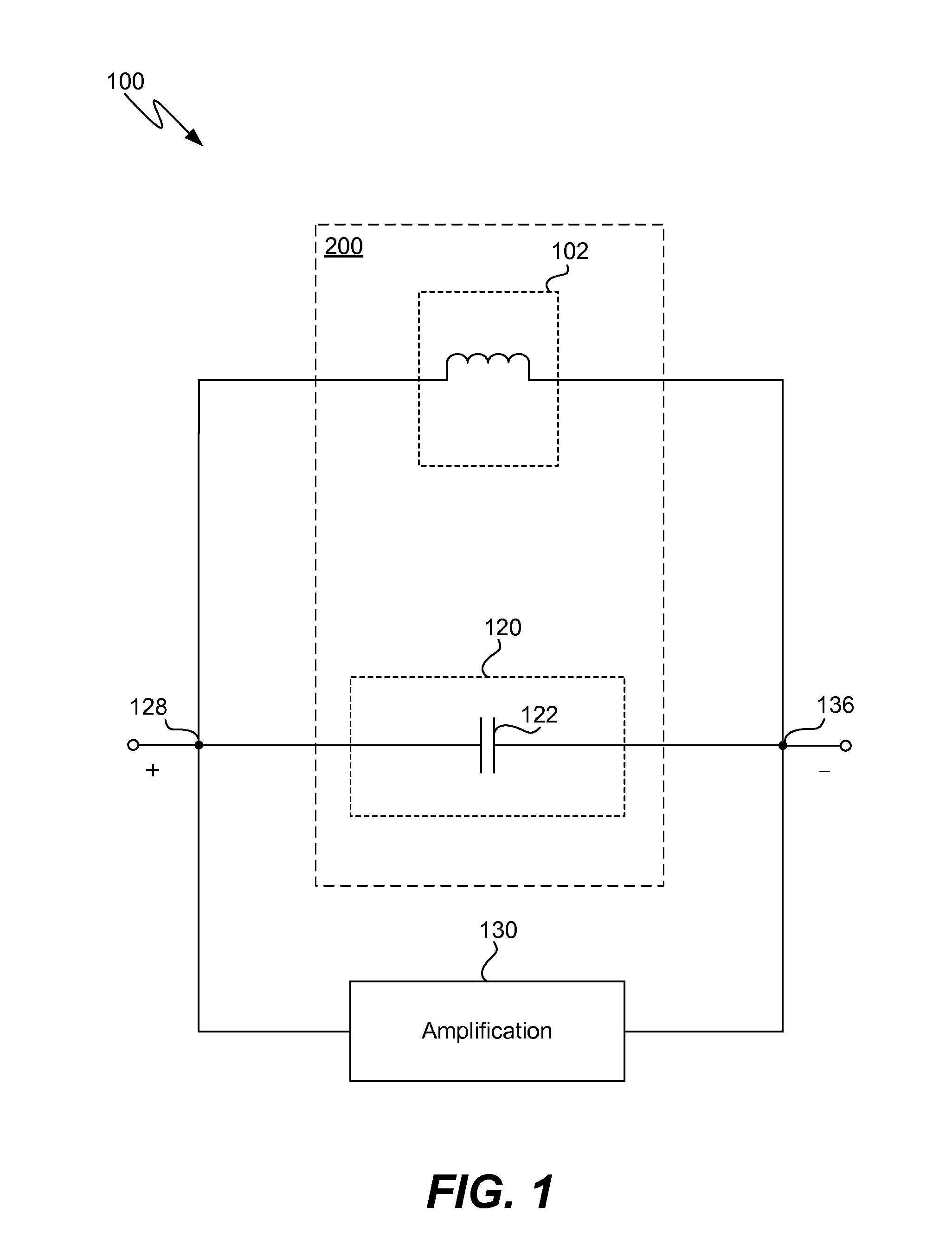
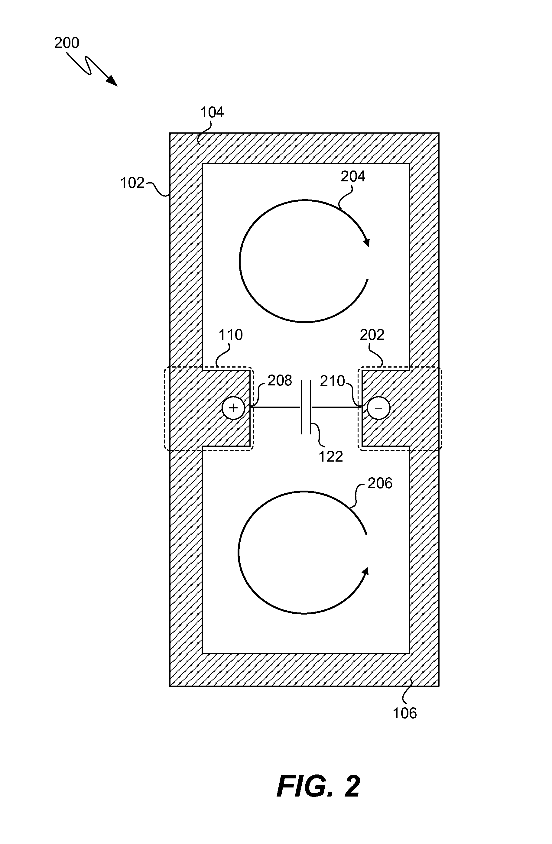
[0018]Referring to FIG. 1, an exemplary LC oscillator circuit (e.g., circuit 100) includes circuit portion 200, which includes an inductor structure 102, and capacitive stage 120, which in at least one embodiment, includes capacitor 122. In at least one embodiment, capacitive stage 120 includes multiple capacitors. In at least one embodiment, capacitive stage 120 includes one or more variable capacitors that change an effective capacitance value of capacitive stage 120 in response to a control signal. In at least one embodiment of circuit portion 200, capacitive stage 120 includes one or more finger capacitor structures formed in one or more conductive integrated circuit layers.

[0019]In at least one embodiment, capacitor 122 stores energy in an electric field in response to a voltage across terminals 128 and 136. In the absence of a voltage on terminals 128 and 136, capacitor 122 discharges and generates a current through inductor structure 102, thereby transferring energy to a magn...


PUM


Abstract

An apparatus includes a first conductive loop coupled to conduct a first current and a second conductive loop coupled in parallel with the first conductive loop and further coupled to conduct a second current. A first conductive portion forms a part of the first conductive loop and the second conductive loop. The first conductive portion is coupled to conduct the first current and the second current. In at least one embodiment of the apparatus, the first conductive loop and the second conductive loop are planar inductors formed in a conductive layer on a substrate of an integrated circuit.

Description

BACKGROUND[0001]1. Field[0002]The present application is generally directed to integrated circuits and more specifically to integrated circuits that include inductors.[0003]2. Description of the Related Art[0004]In general, electronic devices use inductors to store energy in magnetic fields. For example, integrated circuit oscillators (e.g., inductor-capacitor (LC) “tank” circuits) use inductors to generate oscillating signals for certain applications (e.g., inclusion in a narrow bandwidth phase-locked loop (PLL)). However, in those integrated circuit applications, a low-noise, high-Q (i.e., quality factor) LC oscillator is typically required. It is difficult to achieve a low-noise, high Q (e.g., Q>20) LC oscillator with conventional integrated circuit techniques. In addition, the inductors of the LC oscillator circuits are susceptible to electromagnetic interference from external sources of noise.SUMMARY[0005]In at least one embodiment of the invention, an apparatus includes a f...

Claims


Application Information

Patent Timeline
IPC IPC(8): H03B1/00H01F27/29H01F27/28
CPCH01F27/2804H03B5/08
Inventor ELDREDGE, ADAM B.HARA, SUSUMU
Owner SILICON LAB INC
Why Eureka
Try Eureka