
System forTransmission of Signals in a Domestic Environment

a signal and system technology, applied in the field of system for signal transmission in a domestic environment, can solve the problems of poor signal to noise ratio, inability to provide a return channel, and rapid deterioration of bitra

Active Publication Date: 2013-04-04
INTERDIGITAL CE PATENT HLDG
View PDF8 Cites 7 Cited by
  • Summary
  • Abstract
  • Description
  • Claims
  • Application Information

AI Technical Summary

Benefits of technology

The patent proposes a system for improving the reception of signals in a MIMO transmission system. The system includes a central terminal and at least one client terminal with transmission channels and antennas. The central terminal has a control means that selects the best antenna for transmitting signals to the client terminal based on information about the reception quality of the signals. The system also includes an estimation device that generates information about the reception quality of signals in a specific geographic zone where the client terminal is located. This information is used to optimize the reception of the signals. The system also includes a measurement circuit with RFID sensors to measure the power of signals in the specific geographic zones and RFID readers to measure the variations of the transmission channel. The system can be used in various applications such as wireless communication, radar, and imaging.

Problems solved by technology

For longer distances or in more difficult conditions for transmission (poor signal to noise ratio), the bitrate deteriorates rapidly.
This deterioration being essentially due to the fact that the transmitter has no information on the state of the transmission channel.
As for the spatial multiplexing, this technique does not provide for a return channel in order to receive information on the transmission channel.
The majority of these systems do not have a return channel required for the implementation of the beamforming technique.
But, this return channel is not implemented in MIMO technology due to the complexity of the implementation of this return channel.
This reciprocal hypothesis is not valid in an environment dominated by interferences and rich in multiple paths corresponding to a domestic environment.
But as indicated previously, its implementation would lead to a significant increase on the processing part of the signal in the transmitter due to the great number of MIMO antennas and radio channels associated.
Such a solution would be complex to implement, energy consuming and costly.

Method used


Image

  • System forTransmission of Signals in a Domestic Environment
  • System forTransmission of Signals in a Domestic Environment
  • System forTransmission of Signals in a Domestic Environment

Examples


Embodiment Construction

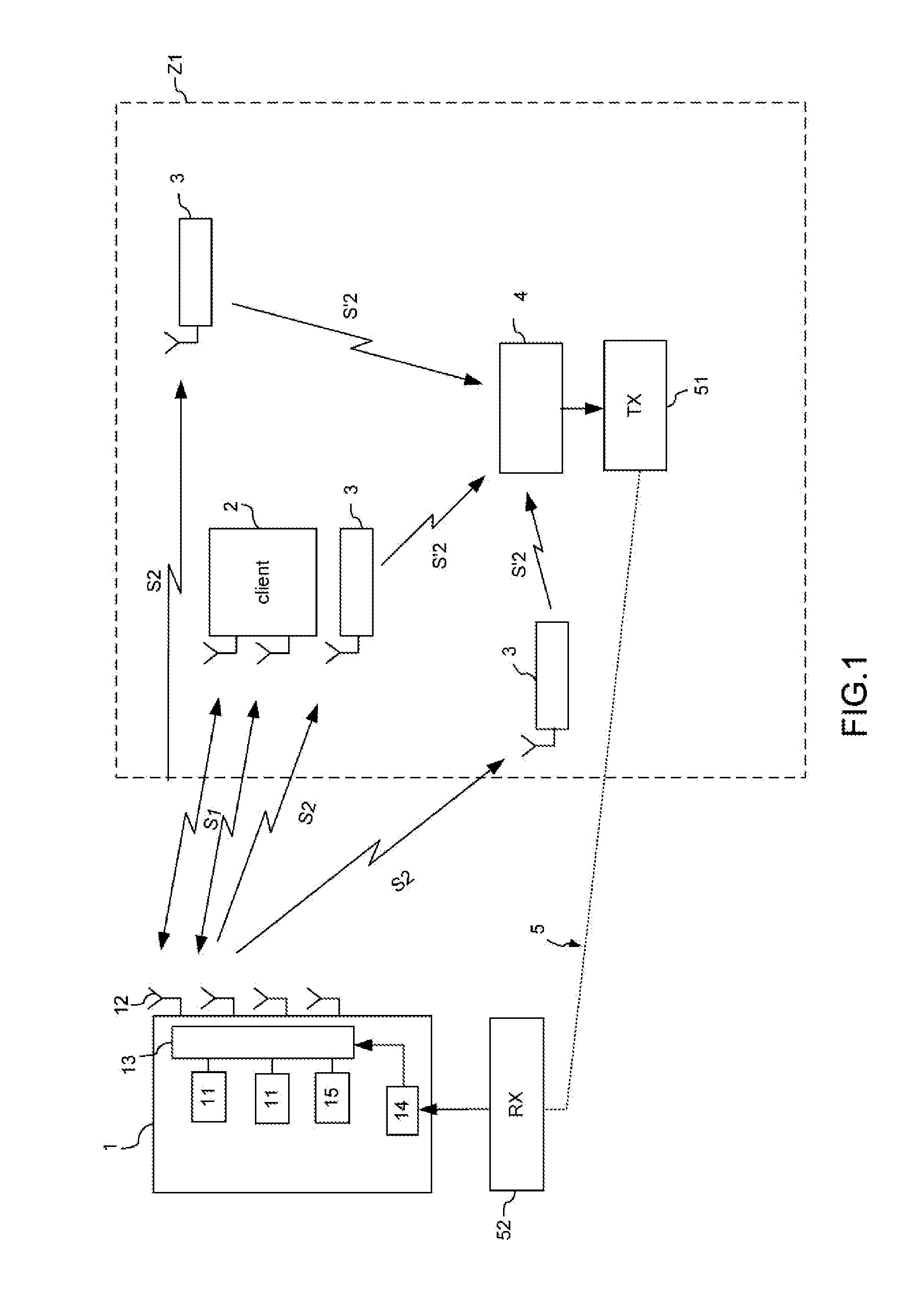
[0044]In reference to FIG. 1, the signals transmission system comprises a central terminal or access point 1 equipped with a plurality of transmission channels 11 and a plurality of directive transmission antennas 12 to transmit signals S1 compliant with, for example, the wireless communication standard 802.11n to at least one client terminal 2.

[0045]The access point 1 is for example located close to an Internet network access and communicates with a client terminal 2, that is for example a multimedia terminal such as a computer, a television, a 3G telephone or an Internet network connector.

[0046]The access point 1 comprises m transmission channels 11 and n transmission antennas 12, with n>m>1. It also comprises switching means 13 in order to associate with each of the m signal transmission channels one antenna among the n antennas according to a switching schema selected by the control means 14. According to a particular embodiment, the switching schema is selected from among a plu...


PUM


Abstract

The present invention relates to a wireless transmission system for signals intended more specifically for a domestic environment. It includes a central terminal comprising at least m transmission channels and n directive transmission antennas intended to transmit first signals at least one client terminal having at least one reception channel connected to a reception antenna in order to receive the first signals said central terminal and said client terminal communicating in a transmission channel having a predetermined frequency band, and an estimation device able to generate an item of information representative of the reception quality of first signals in at least one point of a predetermined geographic zone associated with the client terminal and a return channel in order to transmit said at least one item of information to the control means of the central terminal.

Description

TECHNICAL DOMAIN OF THE INVENTION[0001]The present invention relates to a wireless transmission system for signals intended more specifically for a domestic environment.TECHNOLOGICAL BACKGROUND[0002]The increase in the number of digital multimedia devices in residences has led to the appearance of domestic networks assuring the simultaneous distribution and at a high bitrate of data streams, such as High Definition (HD) video data streams, audio data streams or Internet data streams, these data being available at all or almost all points of the residence. Such a network, for which the structure is dependent on the distribution of rooms within the building (apartment, house with or without a second floor, etc.) in which it is installed, can be deployed using different technologies such as cable, Power Line Carrier (PLC), optical fibre or WiFi type wireless devices complying with the standards 802.11a / b / g or 11n. This latter standard authorizes the use of MIMO (Multiple Input Multiple...

Claims


Application Information

Patent Timeline
Patent Type & Authority Applications(United States)
IPC IPC(8): H04B17/00H04B7/06
CPCH04B7/0417H04B7/0491H04B17/318H04B7/0604H04B17/0057H04B7/0632H04L25/0202H04B5/73H04B5/77
Inventor ROBERT, JEAN-LUCLOUZIR, ALILO HINE TONG, DOMINIQUEPINTOS, JEAN-FRANCOIS
Owner INTERDIGITAL CE PATENT HLDG
Learn More