Bidirectional shift register

a shift register and register technology, applied in the field of shift registers, can solve problems such as multi-output problems and multi-output problems, and achieve the effect of improving the picture quality of the display devi

Active Publication Date: 2013-04-04
LG DISPLAY CO LTD
View PDF8 Cites 26 Cited by
  • Summary
  • Abstract
  • Description
  • Claims
  • Application Information

AI Technical Summary

Benefits of technology

[0008]Embodiments of the present invention include a bidirectional shift register in which only a first stage is set in forward driving and only a last stage is set in reverse driving, thereby preventing generation of a multi-output from any one stage in the forward driving and reverse driving and thus improving picture quality of a display device employing this shift register.

Problems solved by technology

For this reason, in the forward driving, a set node of the last stage floats by the start pulse, resulting in a multi-output problem that the last stage outputs two scan pulses for one frame period.
Likewise, in the reverse driving, a set node of the first stage floats by the start pulse, resulting in a multi-output problem that the first stage outputs two scan pulses for one frame period.

Method used


Image

  • Bidirectional shift register
  • Bidirectional shift register
  • Bidirectional shift register

Examples


first embodiment

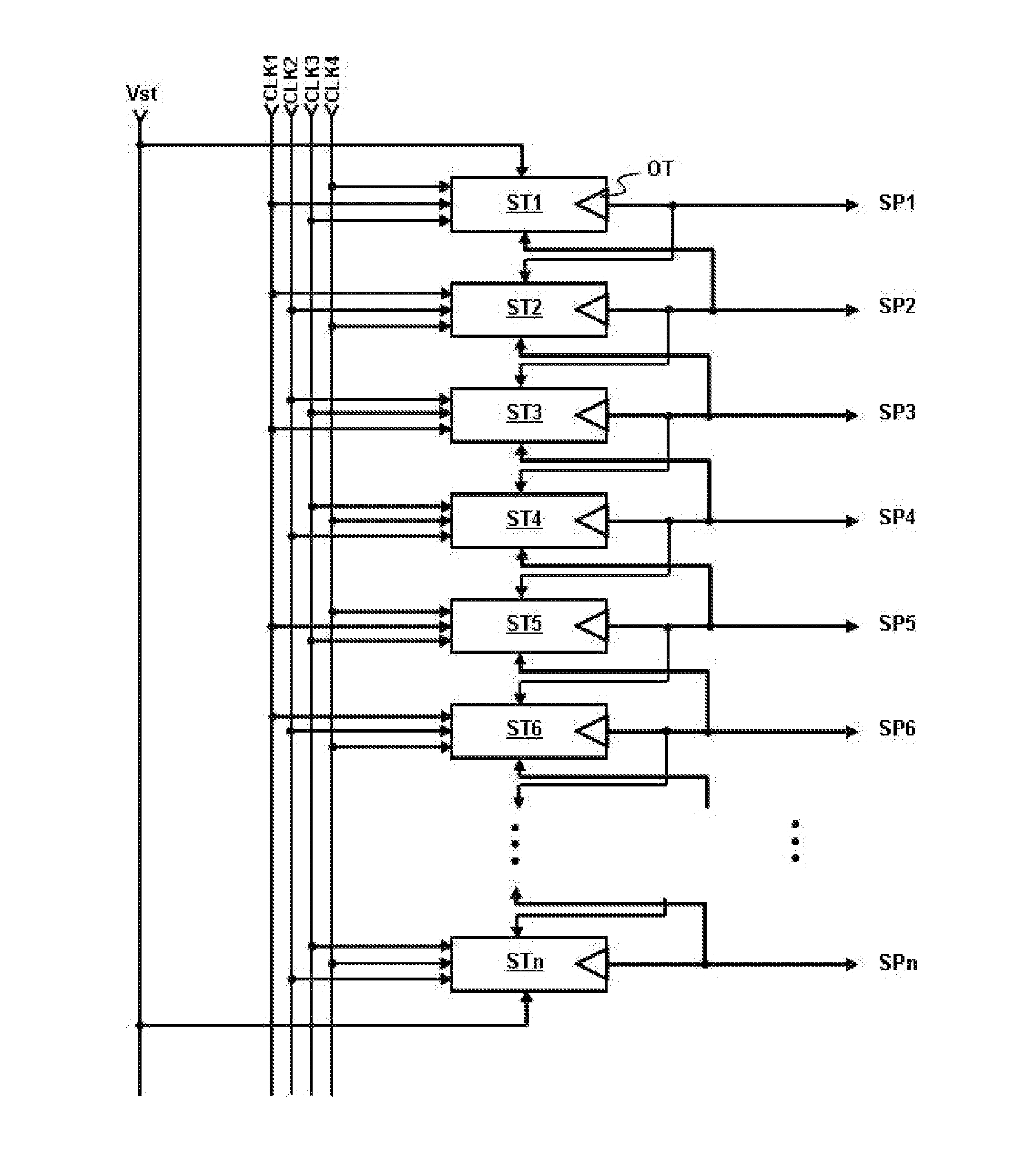
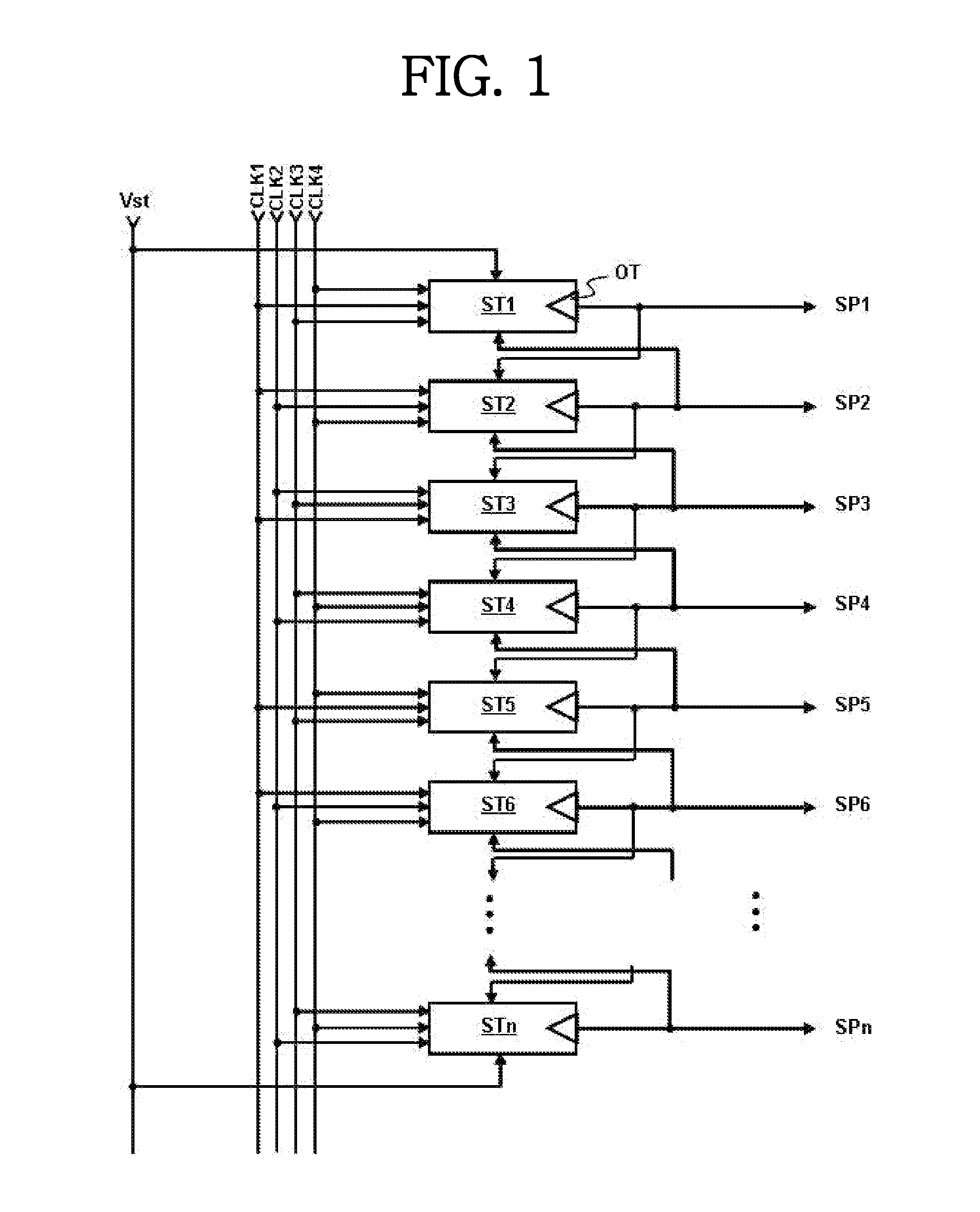
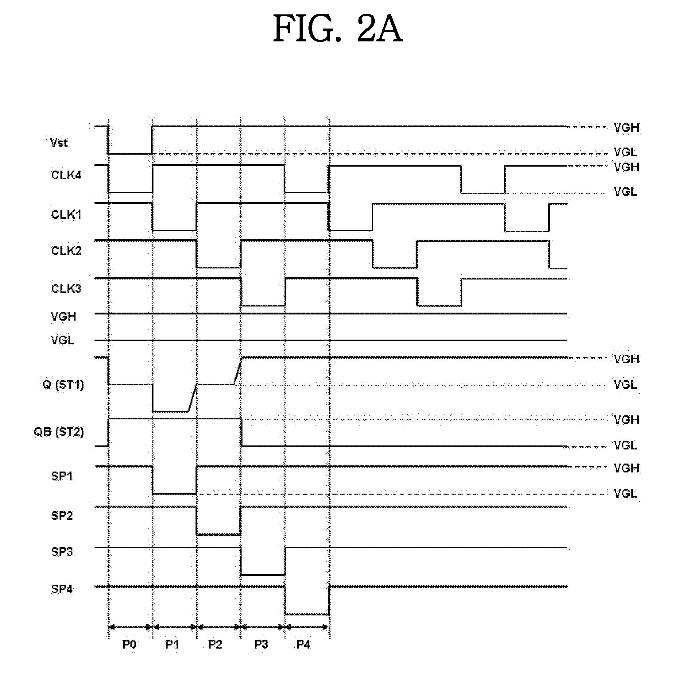
[0055]FIG. 1 is a block diagram showing the configuration of a bidirectional shift register according to the present invention, FIG. 2A is a timing diagram of various signals which are supplied to and output from the bidirectional shift register of FIG. 1 when this bidirectional shift register is driven in a forward mode, and

[0056]FIG. 2B is a timing diagram of various signals which are supplied to and output from the bidirectional shift register of FIG. 1 when this bidirectional shift register is driven in a reverse mode.

[0057]The bidirectional shift register according to the first embodiment of the present invention includes n stages ST1 to STn, as shown in FIG. 1. Each of the stages ST1 to STn outputs one scan pulse SP1 to SPn for one frame period through an output terminal OT thereof.

[0058]Each of the stages ST1 to STn drives a gate line connected thereto using the scan pulse. Also, each of the stages ST1 to STn controls the operations of a stage downstream therefrom and a stage...

second embodiment

[0137]FIG. 7 is a block diagram showing the configuration of a bidirectional shift register according to the present invention.

[0138]The bidirectional shift register according to the second embodiment of the present invention includes n stages ST1 to STn and a start selector SSB, as shown in FIG. 7.

[0139]Each of the stages ST1 to STn outputs one scan pulse SP1 to SPn for one frame period through an output terminal OT thereof.

[0140]Each of the stages ST1 to STn drives a gate line connected thereto using the scan pulse. Also, each of the stages ST1 to STn controls the operations of a stage downstream therefrom and a stage upstream therefrom using the scan pulse.

[0141]When the shift register is driven in a forward mode, the stages ST1 to STn output the scan pulses in order from the first stage ST1 to the last stage STn. That is, the first stage ST1 outputs the first scan pulse SP1, the second stage ST2 then outputs the second scan pulse SP2, the third stage ST3 then outputs the third s...

third embodiment

[0159]FIG. 10 is a block diagram showing the configuration of a bidirectional shift register according to the present invention.

[0160]The bidirectional shift register according to the third embodiment of the present invention includes a plurality of stages ST1 to STn and a start selector SSB, as shown in FIG. 10. The stages ST1 to STn in the third embodiment are the same as the stages ST1 to STN in the second embodiment, stated above.

[0161]In the third embodiment, the start selector SSB includes a forward selection switching device TFS and a reverse selection switching device TRS which are composed of P-type transistors. As shown in FIG. 10, a forward selection signal FSS is applied to the gate electrode of the forward selection switching device TFS, whereas a reverse selection signal RSS is applied to the gate electrode of the reverse selection switching device TRS. The forward selection signal FSS is kept at the activation voltage VGL when the shift register is driven in the forwa...


PUM


Abstract

Disclosed herein is a bidirectional shift register which is capable of preventing multi-outputs from both end stages. The shift register includes a plurality of stages for outputting scan pulses forward or reversely based on a start pulse and a plurality of clock pulses with a phase difference. A last one of the stages includes a forward scan controller for making a set node active and a reset node inactive based on any one of the clock pulses and a scan pulse from an upstream stage, a reverse scan controller for making the set node active and the reset node inactive based on any one of the clock pulses and the start pulse, and an output unit for outputting any one of a corresponding scan pulse and a deactivation voltage based on a voltage at the set node, a voltage at the reset node and any one of the clock pulses.

Description

CROSS-REFERENCE TO RELATED APPLICATION[0001]This application claims the benefit of Korean Patent Application No. 10-2011-0100521, filed on Oct. 4, 2011 which is hereby incorporated by reference as if fully set forth herein.BACKGROUND OF THE INVENTION[0002]1. Field of the Invention[0003]The present invention relates to a shift register, and more particularly, to a bidirectional shift register which is capable of preventing multi-outputs from both end stages.[0004]2. Discussion of the Related Art[0005]A bidirectional shift register, which is capable of outputting scan pulses forward or reversely, includes a plurality of stages. In particular, a start pulse is always supplied to a first stage and a last stage at the beginning of driving irrespective of forward driving or reverse driving.[0006]For this reason, in the forward driving, a set node of the last stage floats by the start pulse, resulting in a multi-output problem that the last stage outputs two scan pulses for one frame perio...

Claims


Application Information

Patent Timeline
Patent Type & Authority Applications(United States)
IPC IPC(8): G11C19/00
CPCG11C19/28G09G3/20G09G2310/0286
Inventor LEE, JI-NOHA, SANG-MYUNGKIM, TAE-SANGKIM, JONG-KYUNG
Owner LG DISPLAY CO LTD
Why Eureka
Try Eureka