Plasma-Tuning Rods in Surface Wave Antenna (SWA) Sources

Inactive Publication Date: 2013-04-04
TOKYO ELECTRON LTD
View PDF7 Cites 11 Cited by
  • Summary
  • Abstract
  • Description
  • Claims
  • Application Information

AI Technical Summary

Benefits of technology

[0009]The invention relates to SWA processing systems and, more particularly, to SWA processing systems having at least one plasma-tuning rod for creating large stable and/or uniform plasma systems.
[0010]According to embodiments, a plurality of SWA plasma sources are described. In some embodiments, the SWA plasma sources can comprise one or more non-circular slot antennas, each having a plurality of plasma-tuning rods extending therethrough. Some of the plasma tuning rods can be configured to couple the electromagnetic (EM) energy from one or more of the non-circular slot antennas to the process space within the process chamber.
[0011]In other embodiments, the SWA plasma sources can comprise a plurality of resonant cavities, each having one or more plasma-tuning rods extending therefrom. Some of the plasma tunin

Problems solved by technology

However, the practical implementation of microwave resonator systems still suffers

Method used


Image

  • Plasma-Tuning Rods in Surface Wave Antenna (SWA) Sources
  • Plasma-Tuning Rods in Surface Wave Antenna (SWA) Sources
  • Plasma-Tuning Rods in Surface Wave Antenna (SWA) Sources

Examples


Embodiment Construction

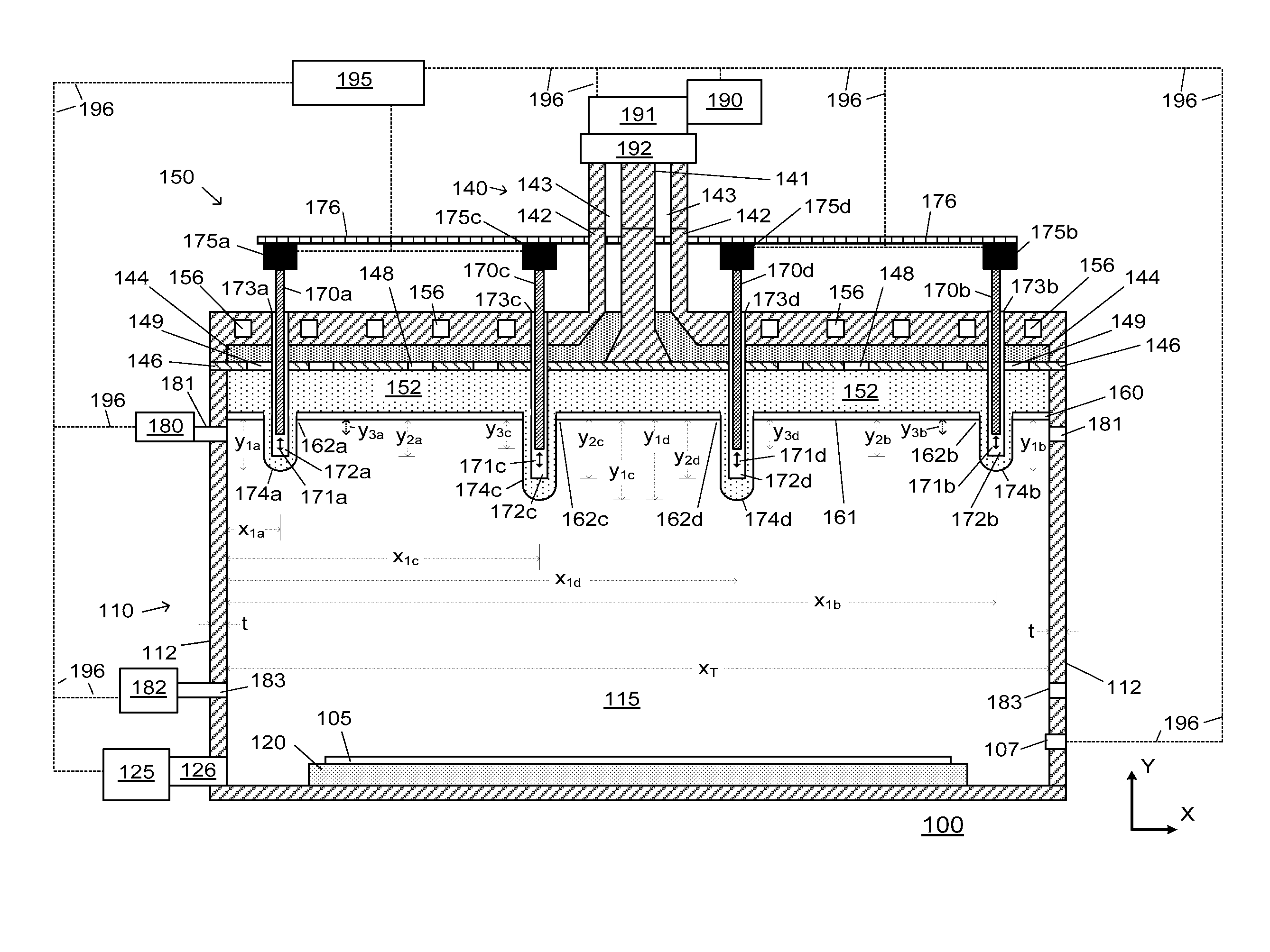
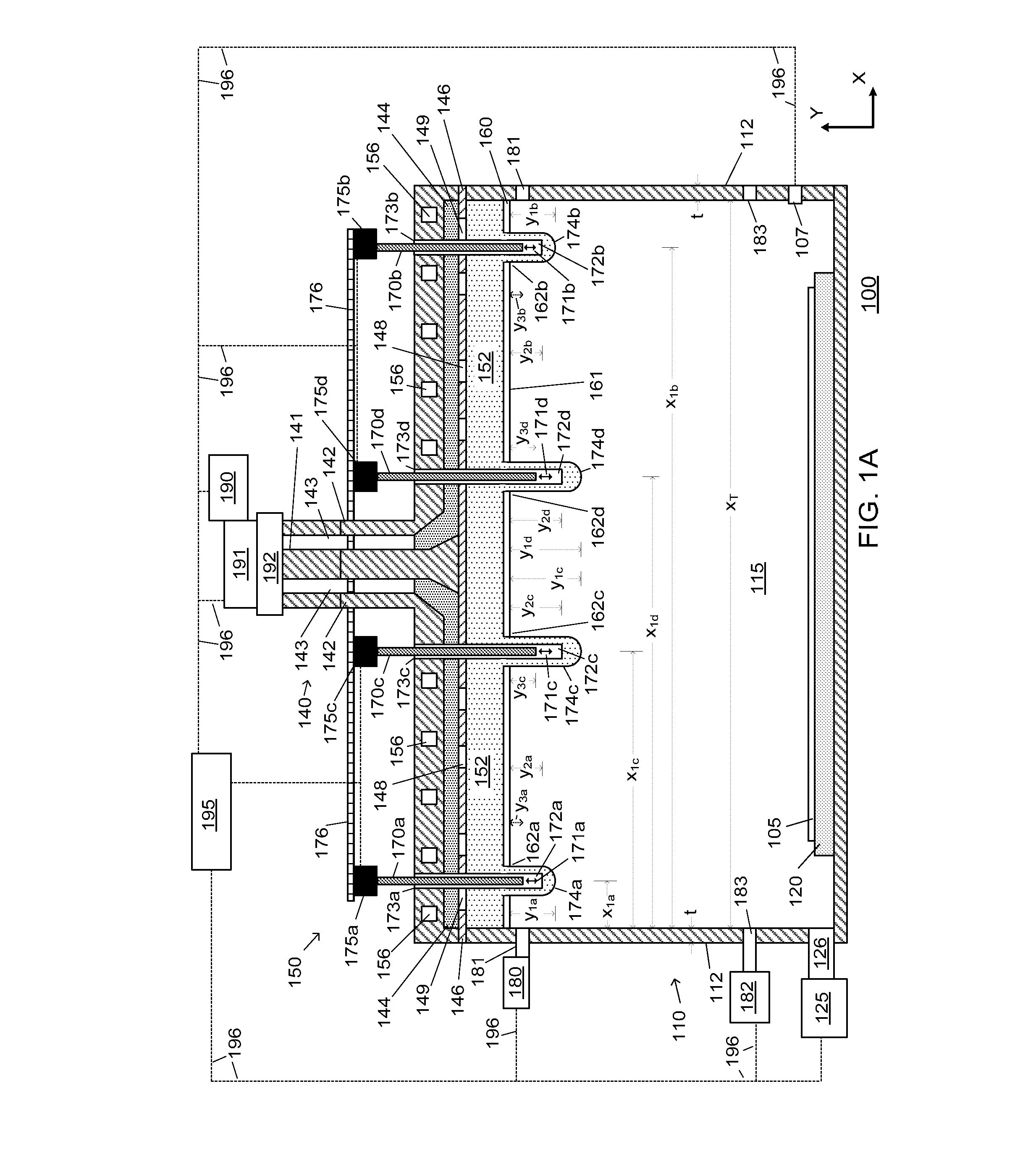
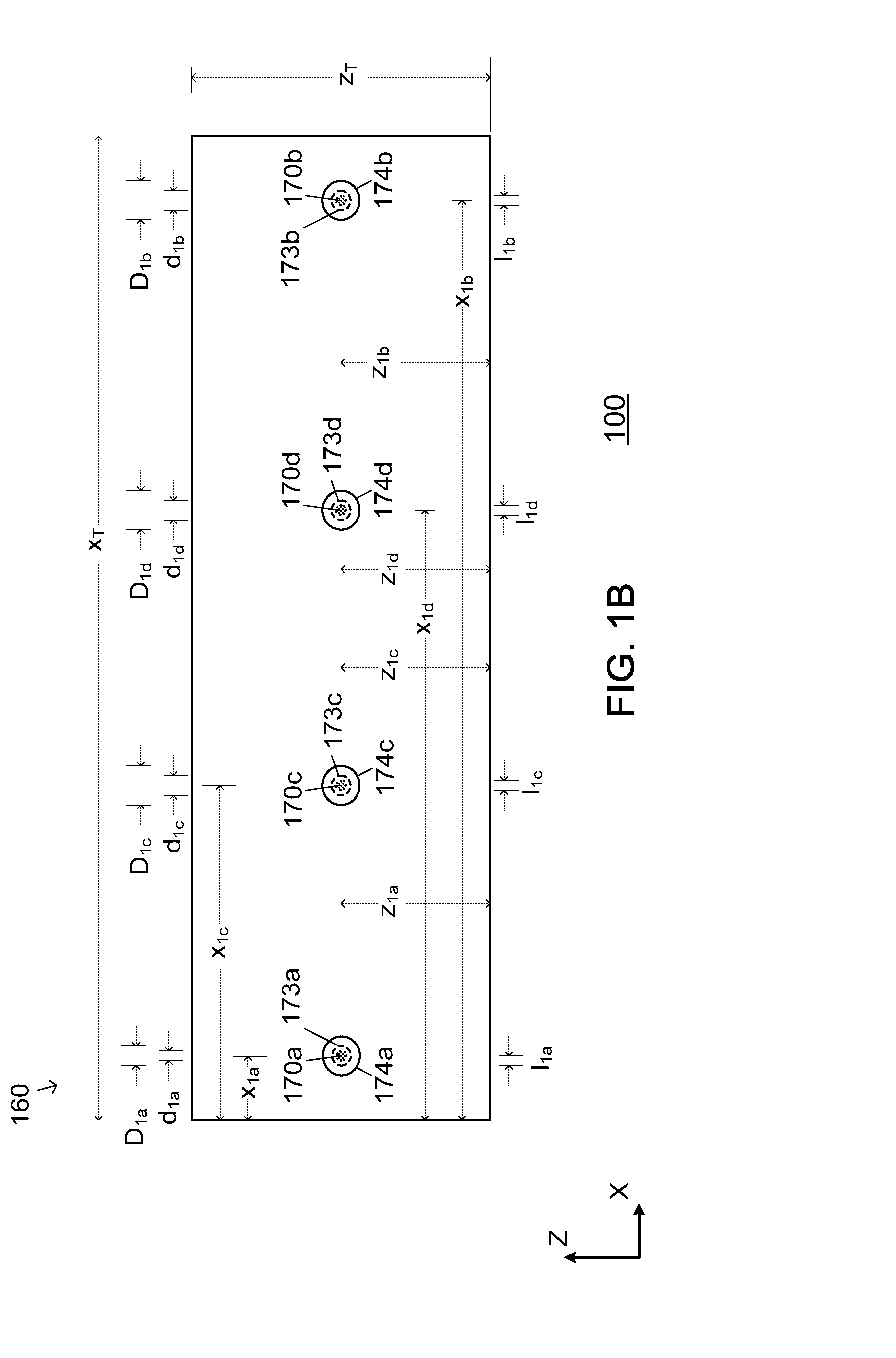
[0023]SWA plasma sources and SWA processing systems are disclosed in various embodiments. However, one skilled in the relevant art will recognize that the various embodiments may be practiced without one or more of the specific details, or with other replacement and / or additional methods, materials, or components. In other instances, well-known structures, materials, or operations are not shown or described in detail to avoid obscuring aspects of various embodiments of the invention.

[0024]Similarly, for purposes of explanation, specific numbers, materials, and configurations are set forth in order to provide a thorough understanding of the invention. Nevertheless, the invention may be practiced without specific details. Furthermore, it is understood that the various embodiments shown in the figures are illustrative representations and are not necessarily drawn to scale.

[0025]Reference throughout this specification to “one embodiment” or “an embodiment” or variation thereof means tha...


PUM

PropertyMeasurementUnit
Timeaaaaaaaaaa
Frequencyaaaaaaaaaa
Frequencyaaaaaaaaaa

Abstract

The invention provides a plurality of Surface Wave Antenna (SWA) plasma sources. The SWA plasma sources can comprise one or more non-circular slot antennas, each having a plurality of plasma-tuning rods extending therethrough. Some of the plasma tuning rods can be configured to couple the electromagnetic (EM) energy from one or more of the non-circular slot antennas to the process space within the process chamber. The invention also provides SWA plasma sources that can comprise a plurality of resonant cavities, each having one or more plasma-tuning rods extending therefrom. Some of the plasma tuning rods can be configured to couple the EM energy from one or more of the resonant cavities to the process space within the process chamber.

Description

CROSS-REFERENCE TO RELATED APPLICATIONS[0001]This application is related to co-pending U.S. patent application Ser. No. 13 / ______, attorney docket No. TEA-074, entitled “Plasma Tuning Rods in Microwave Resonator Plasma Sources”, filed on even date herewith. This application is related to co-pending U.S. patent application Ser. No. 13 / ______, attorney docket No. TEA-071, entitled “Plasma Tuning Rods in Microwave Processing Systems”, filed on even date herewith. The contents of each of these applications are herein incorporated by reference in their entireties.BACKGROUND OF THE INVENTION[0002]1. Field of the Invention[0003]The present invention relates to substrate / wafer processing, and more particularly to Surface Wave Antenna (SWA) processing systems and methods for processing substrates and / or semiconductor wafers using SWA processing systems.[0004]2. Description of the Related Art[0005]Typically, during semiconductor processing, a (dry) plasma etch process is utilized to remove or...

Claims


Application Information

Patent Timeline
IPC IPC(8): H01L21/311H01L21/3065
CPCH01J37/3222H01J37/32293H01J37/32256
Inventor ZHAO, JIANPINGCHEN, LEEFUNK, MERRITTIWAO, TOSHIHIKOVENTZEK, PETER L.G.
Owner TOKYO ELECTRON LTD
Why Eureka
Try Eureka